

By Jordi van der Lem

In this blog post, I invite you to join me on my iterative journey toward crafting the final product. I will be discussing the techniques I’ve explored and refined for creating and deforming Terrain, and I’ve provided links to external sources for additional information.
Use Case
Objective:
The primary goal of this project is to develop a robust and customizable infinite procedural terrain generator inspired by the awe-inspiring landscapes of Subnautica. This tool will serve as a foundational asset, empowering me to create expansive and dynamic environments for future game projects, particularly those centered around endless exploration.
Use Case:
Consider a scenario where I am developing a game that emphasizes exploration as its core gameplay mechanic. The infinite procedural terrain generator becomes an indispensable tool in this context, enabling the creation of vast, diverse landscapes that captivate players with uncharted territories, hidden mysteries, and breathtaking vistas.
Target Audience:
This solution is primarily intended for game developers, including myself, who aspire to build games with an emphasis on endless exploration. The tool is designed to streamline the process of generating vast and varied terrains, enhancing the overall gaming experience by eliminating the constraints of predefined maps. It caters to individuals or teams working on projects where exploration, discovery, and the seamless integration of diverse landscapes are pivotal aspects.
Conclusion:
By creating this infinite procedural terrain generator, the aim is not only to facilitate the development of a specific game but to lay the groundwork for a versatile tool that can be utilized across various game projects. This solution empowers developers, including myself, to bring to life games where exploration knows no bounds, offering players a truly immersive and endlessly fascinating experience.
Challenges I aim to address with each iteration of the Project.
- Efficiently creating terrain
- Expand ability of terrain
- Noise layering
- Deformation capability
Definitions of specific terms
- “Perlin Noise” – a continuous gradient noise function invented by Ken Perlin, producing a smoothly varying and natural-looking sequence of pseudo-random values[3].
- “Chunk” – a slice of landscape. when a lot are connected together it makes the world or a bigger landscape
Iteration 1 – Begin of terrain
During the first iteration, I tried to address the three previously mentioned challenges in the following manner:
Creating smooth terrain – Efficiently creating terrain
When considering terrain generation, I initially thought about a method similar to Minecraft. However, Minecraft has a distinct blocky appearance, lacking the smoothness found in games like Subnautica or Deep Rock Galactic. After conducting some research, I discovered an algorithm capable of generating a less blocky environment. Drawing inspiration from Polycoding’s example[1] and receiving advice from experts in my field, I explored cube marching as an alternative to simply spawning cubes in a grid.

Here, you observe the Minecraft algorithm, which involves placing cubes on points connected by Perlin noise. While this is a functional algorithm, it produces a blocky outline, which is not suitable for my requirements.
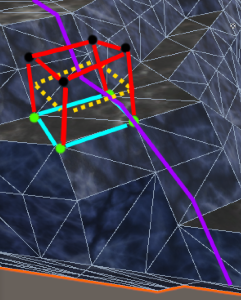
In the Cube Marching algorithm, it generates a face based on points located below the yellow slice, positioned where the purple line (Perlin noise) intersects the cube of points, contributing to a notably smoother surface.
Setting up cube marching.
In Cube Marching, the Edge Table and Corner Table are vital tools for identifying cube corners and determining edges connecting points inside or outside the Perlin noise.
    public static Vector3Int[] CornerTable = new Vector3Int[8] {

        new Vector3Int(0, 0, 0),
        new Vector3Int(1, 0, 0),
        new Vector3Int(1, 1, 0),
        new Vector3Int(0, 1, 0),
        new Vector3Int(0, 0, 1),
        new Vector3Int(1, 0, 1),
        new Vector3Int(1, 1, 1),
        new Vector3Int(0, 1, 1)

    };

    public static int[,] EdgeTable = new int[12, 2] {

     {0,1}, {1,2 }, {3,2 }, {0,3 }, {4,5 }, {5,6 },{7,6 },{4,7 },{0,4 },{1,5 },{2,6 },{3,7}

    };
The Edge Table guides the algorithm, illustrating edge positions in the cube and highlighting regions beyond or within the Perlin noise. This information is crucial for intelligent surface creation.
Simultaneously, the Corner Table acts as a map, specifying corner placement within or outside the Perlin noise. This aids the algorithm in vertex positioning, ensuring surfaces align seamlessly with desired terrain contours.
Together, these tables enhance Cube Marching’s adaptability, allowing dynamic adjustments based on corner and edge relationships. This ensures terrain aligns with the intricacies of the underlying Perlin noise.
    public static int[,] TriangleTable = new int[,] {

        {-1, -1, -1, -1, -1, -1, -1, -1, -1, -1, -1, -1, -1, -1, -1, -1},
        {0, 8, 3, -1, -1, -1, -1, -1, -1, -1, -1, -1, -1, -1, -1, -1},
        {0, 1, 9, -1, -1, -1, -1, -1, -1, -1, -1, -1, -1, -1, -1, -1},
        {1, 8, 3, 9, 8, 1, -1, -1, -1, -1, -1, -1, -1, -1, -1, -1},
        {1, 2, 10, -1, -1, -1, -1, -1, -1, -1, -1, -1, -1, -1, -1, -1},
        {0, 8, 3, 1, 2, 10, -1, -1, -1, -1, -1, -1, -1, -1, -1, -1},
        {9, 2, 10, 0, 2, 9, -1, -1, -1, -1, -1, -1, -1, -1, -1, -1},
        {2, 8, 3, 2, 10, 8, 10, 9, 8, -1, -1, -1, -1, -1, -1, -1},
        //There are 256 combinations of this so it goes on for a while
In face generation, Cube Marching uses the Triangle table, a key reference for potential triangle arrangements within a cube. It guides vertex connections to create meaningful triangular surfaces.
The Triangle table acts as a lookup during the algorithm, specifying triangulation for voxel states. This dynamic adaptation produces more organic terrains compared to block-based algorithms.
After placing all the faces the terrain is much smoother in the image below you can see the difference in landscape. you can see that the minecraft like landscaping has cubes and really jagged edges. In the marching cubes example you can see it is much smoother and not all cubes


The terrain looks good right now but it is still not a whole world or even a cave system. this is why we need to look at the next problem: the ability to expand the terrain.
The ability to expand the terrain
For the first iteration i wanted to look at how i wanted to build the world i wanted to make it optimal with deformation in mind. this meant that it needed a lot of smaller chunks instead of big chunks because when deforming a chunk it needs to reload the whole chunk. Reloading smaller chunks instead of the whole world is much more efficient.
That is why i create a grid system where all the chunks are spawned in a cubic grid. Each chunk is no bigger than 16x16x16 to account for future deformation ability.
    void Generate()
    {
        chunks.Clear();
        for (int x = 0; x < worldSizeInChunks; x++)
        {
            for (int y = 0; y < worldSizeInChunks; y++)
            {
                for (int z = 0; z < worldSizeInChunks; z++)
                {
                    Vector3Int chuckPos = new Vector3Int(x * GameData.chunkWidth, y * GameData.chunkHeight, z * GameData.chunkWidth); // Calculate the position correctly
                    chunks.Add(chuckPos, new Chunk(chuckPos));
                }
            }
        }
    }
Here you can see a example of how it looks when a 3 chunk size world is generated.
Smoothing out the terrain
The terrain we have right now i pretty nice but still not very smooth. there are jagged adages everywhere and you can see that it is build from triangles instead of a smooth surface. For this i used something pretty simple. To create the smoothness i got the average position between 2 points and than used that height. In the image below you can see a example on how this works.

Here you can see by moving the vertex to the middle point of the planes that the surface is much smoother.

This makes caves look much smoother than before
Noise Layering
Now that the terrain is properly generated and we can generate caves that aren’t made of blocks we can try to manipulate the terrain. For the first iteration i wanted to know how to manipulate the perlin noise so i can generate larger or smaller caves. I got the idea of stacking perlin noise from the video of Henrik Kniberg[2]. Here he explained that you can generate very interesting terrain with stacking noise. I was not familiar with this so i tried to stack the perlin noise on top of one another.
    public static float GetTerrainHeight(int x, int y, int z)
    {
        noise = new FastNoiseLite(); // Initialize the noise object
        noise.SetNoiseType(FastNoiseLite.NoiseType.Perlin);
        noise.SetFrequency(perlinScale);
        noise2 = new FastNoiseLite(); // Initialize the noise object
        noise2.SetNoiseType(FastNoiseLite.NoiseType.Perlin);
        noise2.SetFrequency(perlinScale*10);

        float xCoord = x * perlinScale;
        float yCoord = y * perlinScale;
        float zCoord = z * perlinScale;
        float noiseValue = noise.GetNoise(xCoord, yCoord, zCoord) * (terrainHeightRange*y);
        float noiseValue2 = noiseValue + noise2.GetNoise(xCoord, yCoord, zCoord) * (terrainHeightRange * y);

        float trueNoise2 = (noiseValue2) * (terrainHeightRange * y) + baseTerrainHeight;

        return trueNoise2;
    }
Here, you can observe the generation of Perlin Noise using a variable called “perlinScale.” This reduces the noise intensity, resulting in a less chaotic appearance. In the subsequent images, you’ll notice Perlin noise with a low frequency, creating larger caves, and another with a high frequency, generating smaller caves.


Deformation
Regarding deformation, there’s currently no implementation. The chunks are structured to accommodate future additions without causing performance issues. However, due to time constraints, the inclusion of deformation was not feasible in this iteration. It is, however, set up to seamlessly integrate deformation in the next iteration.
Conclusion
The initial iteration creates a intricate terrain following the designer’s input, which is excellent for VR games. This iteration can be adjusted by adding or reducing vertices to make it less demanding on the computer while maintaining a pleasing appearance. In the upcoming iteration, there should be a focus on optimization since crafting intricate caves remains quite demanding for the hardware. Therefore, an assessment of optimization is necessary to ensure it runs smoothly in VR.
Iteration 2 – Expandable terrain
In this iteration of the perpetual Subnautica terrain generator, my focus will be on two distinct aspects: the expandability of terrain and the capability for deformation. This emphasis is crucial because simply creating a vast cube is insufficient when aiming for an infinite world. Conversely, constructing an excessively large cube for the world size is impractical due to prolonged loading times. I required a mechanism that would generate land chunks as the player moved in different directions, ensuring an endless and seamless terrain experience. Additionally, the capability for deformation is integral to the experience, as it represents the most enjoyable aspect of the terrain. The player gains the ability to shape the terrain as desired, contributing significantly to the immersive and interactive nature of the virtual landscape.
Perpetual terrain generation
To make the perpetual terrain generation i looked at what i had and try to move the terrain as i needed. this created a few challenges. the first challenge was just moving the whole cube. due to how i had created the cube it proved to be quite difficult. This was because when i moved the cube it was not able to handle the position of the player that well and resulted in the whole cube breaking and not even showing up. you can see that in the next image:

In the presented scenario, it’s evident that the attempted spawning of elements failed due to the system’s incapacity to handle non-rounded numbers. This posed a significant challenge, prompting a need to reevaluate the methodology employed for chunk creation and spawning. Since this issue stemmed from intricacies within my own code, there was a scarcity of relevant references for guidance. Consequently, I embarked on a problem-solving journey independently, seeking assistance from fellow students in my field of study.
In addressing the chunk problem, I devised a solution involving the selective spawning of chunks. This approach dictated that chunks would only be spawned when the player reached a specific threshold and at locations defined by whole numbers. Implementing this solution successfully restored the familiar terrain from the past, as depicted in the subsequent image where the terrain is seen to have spawned once again.

Here, you can observe how the chunk spawning operates as the player moves through the terrain. Chunks ahead of the player are generated, while those behind are systematically removed, optimizing the game’s performance.

With the corrected spawning of chunks in place, my next task was to seamlessly incorporate the new chunks while removing those on the opposite side of their creation. Upon implementing this adjustment, the outcome is evident in the accompanying video. Here, you can observe that as I alter the player’s position, the landscape dynamically generates around the player, showcasing the successful integration of the procedural generation mechanism.
 for (int x = 0; x < worldSizeInChunks; x++)
        {
            for (int y = 0; y < worldSizeInChunks; y++)
            {
                for (int z = 0; z < worldSizeInChunks; z++)
                {
                    Vector3Int chuckPos = new Vector3Int(
                        x * GameData.chunkSize + playergridX - (worldSizeInChunks * chunkSize) / 2,
                        y * GameData.chunkSize,
                        z * GameData.chunkSize + playergridZ - (worldSizeInChunks * chunkSize) / 2);

                    if (!chunks.TryGetValue(chuckPos, out Chunk chunk))
                    {
                        chunk = new Chunk(chuckPos);
                        chunks.Add(chuckPos, chunk);
                        chunk.chunkObject.transform.parent = this.transform;
                    }

                    MeshFilter meshFilter = chunk.meshFilter;
                    meshFilters.Add(meshFilter);
                    chunkTransforms.Add(meshFilter.transform);
                    chunksToRemove.Remove(chuckPos);
                }
            }
        }
In the code snippet provided, the generation of chunks is orchestrated with careful consideration for the player’s position. The nested loops iterate through the x, y, and z coordinates of the world, creating chunks based on the specified dimensions. The player’s position influences the placement of the world, ensuring that it is centered around the player’s grid position.
The Vector3Int chunkPos is calculated for each iteration, representing the position of the current chunk in the world. The x, y, and z coordinates are determined by the loop indices and the player’s grid position. The GameData.chunkSize parameter defines the size of each chunk.
Within the nested loops, the code checks if a chunk with the calculated position already exists in the chunks dictionary. If not, a new Chunk object is instantiated at the calculated position, added to the chunks dictionary, and assigned a parent under the current object.
For each newly created or existing chunk, its MeshFilter is obtained and added to the meshFilters list, while the corresponding transform is added to the chunkTransforms list. Additionally, the chunk’s position is removed from the chunksToRemove list, ensuring it is not considered for removal.
In summary, this code snippet demonstrates the creation and management of chunks in a world, with a focus on aligning the world around the player’s position for a dynamic and responsive environment.
Why endless terrain?
The motivation behind crafting this expansive terrain stemmed from my admiration for the Subnautica world, particularly its captivating caves. However, I perceived the original map as somewhat limited in size. Consequently, I endeavored to create an infinite terrain, envisioning a scenario where players could delve into exploration for extended periods without encountering any sense of reaching the map’s end. This design choice guarantees that players can explore to their heart’s content, ensuring an endless and immersive gaming experience.
Deformation
In this particular version, my goal was to introduce a fundamental form of terrain deformation. I aimed to implement a simplistic point-and-click mechanism allowing users to either add or remove terrain at specific points. To guide my approach, I referred to a tutorial video [insert link here], which demonstrated modifying terrain by altering the generation process and subsequently regenerating the entire chunk. While I attempted to integrate this technique, the current implementation falls short of the desired extent. Further refinement is necessary in subsequent iterations to enhance the functionality and achieve the desired outcome for the final product.
public void PlaceTerrain(Vector3 pos)
{
    Vector3Int v3Int = new Vector3Int(Mathf.CeilToInt(pos.x), Mathf.CeilToInt(pos.y), Mathf.CeilToInt(pos.z));
    v3Int -= chunkPosition;
    terrainMap[v3Int.x, v3Int.y, v3Int.z] = 0f;
    ClearMeshData();
    CreateMeshData();
}

public void RemoveTerrain(Vector3 pos)
{
    Vector3Int v3Int = new Vector3Int(Mathf.FloorToInt(pos.x), Mathf.FloorToInt(pos.y), Mathf.FloorToInt(pos.z));
    v3Int -= chunkPosition;
    terrainMap[v3Int.x, v3Int.y, v3Int.z] = 1f;

    ClearMeshData();
    CreateMeshData();
}
In the provided code, two methods, PlaceTerrain and RemoveTerrain, handle the addition and removal of terrain within a chunk.
PlaceTerrain Method:
This method is responsible for adding terrain at the specified position. The input position (pos) is first converted to integer coordinates (v3Int) using Mathf.CeilToInt. This ensures that the terrain is placed at the top of the specified position. The calculated integer coordinates are then adjusted based on the chunk’s position, and the corresponding value in the terrainMap array is set to 0 (indicating terrain presence). Subsequently, the mesh data is cleared, and new mesh data is created to reflect the updated terrain.
RemoveTerrain Method:
Conversely, the RemoveTerrain method removes terrain at the specified position. Similar to the PlaceTerrain method, the input position is converted to integer coordinates (v3Int) using Mathf.FloorToInt to ensure terrain removal from the bottom of the specified position. The adjusted coordinates are then used to set the corresponding value in the terrainMap array to 1 (indicating absence of terrain). The mesh data is cleared, and new mesh data is generated to reflect the modified terrain.
In essence, these methods facilitate the dynamic modification of terrain within the chunk by updating the terrain Map array and regenerating the mesh data accordingly.

In this snapshot, I’ve both added and removed terrain. Notably, the absence of smooth stepping when incorporating the additional terrain results in a jagged and unfinished appearance. Despite this, the foundational aspects of terrain deformation are now integrated into the game, marking a successful accomplishment of one of the objectives for this iteration.
In the following images, you can witness the actual mechanics of the deformation process. These images illustrate the creation of terrain between specified points. The deformation operates by toggling the state of the point you are focusing on and activating the one behind or in front of it, depending on whether you are excavating or constructing terrain. Here, both a 2D and a 3D representation of the terrain deformation are provided.


Why deformation?
I opted for terrain deformation to empower players to craft more personalized worlds and embark on exploration in unique and captivating ways. Games like Minecraft and Deep Rock Galactic, where you can alter terrain, unveil vast caves, and discover hidden caverns, greatly inspired this choice. Integrating deformation into my terrain generation adds an intriguing dimension, especially considering the limitless expanse of my terrain, making it fascinating for players to dig through the ground and uncover new possibilities.
Conclusion
In this iteration, my primary focus was on achieving true endlessness and deformability within the world. I made this choice because I aim to provide an experience where the underwater terrain feels boundless. Drawing inspiration from the game “Subnautica,” I admired its terrain but found it somewhat limited. Thus, my goal is to make my terrain truly infinite, ensuring that the exploration never ceases, allowing players to enjoy an endless adventure.
While the essential functions are in place, they still require significant improvement. For instance, the terrain deformation currently exhibits spikiness and doesn’t seamlessly traverse across chunks as intended. Another challenge is that although the terrain is endless, there is a delay in loading new chunks when the player moves. Consequently, in the upcoming iteration, my focus will be on enhancing performance, specifically addressing the seamless spawning of new chunks without causing lag.
Iteration 3 – Performance
In this iteration, I aimed to prioritize performance. While the terrain currently looks impressive, the loading times are excessively long. With the goal of ensuring a seamless experience, especially when navigating the terrain underwater, I delved deeper into optimizing performance.
Research
Before delving into optimization, I needed to identify the specific area to enhance. Following discussions with my teachers and conducting tests to identify bottlenecks, I concluded that optimizing the calculations for the terrain shape was paramount. The rationale behind this choice is rooted in the fact that terrain calculations involve a substantial number of computations, and the GPU (Graphics Processing Unit) is more adept at handling parallel tasks compared to the CPU (Central Processing Unit).
To clarify, the CPU is the computer’s processor responsible for managing smaller, sequential calculations and executing tasks one after the other. On the other hand, the GPU is optimized for parallel processing, allowing it to handle multiple tasks simultaneously. In light of this, I explored Compute Shading, leveraging the CPU to perform the millions of calculations required for terrain shape optimization.
Because I didn’t know how Compute Shaders work, let alone understand the strengths of the GPU, I needed to conduct thorough research. Information about the GPU and its parallel computing capabilities was gathered from various tutorials on the topic. For instance, I found a well-explained tutorial video by Game Dev Guide[8] that provided a solid foundation. Subsequently, I sought inspiration and practical insights by watching a video by Will Hess[9].
Now armed with a foundational understanding of Compute Shading and some creative ideas, the next step is to articulate a comprehensive explanation of its functioning, why it’s effective, and how I intend to integrate it into my project.
Compute Shading
Compute shading is a pretty difficult task within the game development environment because it uses a different coding style than the most used styles and the one that i made for this project. but that did not hold me back from discovering how Compute shaders really work. Because i want to spare you the hours of watch tutorials of how it works i will say it compact with some examples.
CPU VS GPU
As mentioned earlier, the GPU excels at parallel computation, in contrast to the sequential nature of the CPU. But what exactly does this entail? The images below provide an explanation of why this parallel processing capability is exceptionally advantageous when dealing with substantial volumes of data, such as in my terrain generation.
Here, you can observe the CPU calculating the chunk positions sequentially, one after another. Now, envision having to repeat this process 4000 times — a task that would undoubtedly consume a considerable amount of time.
In this context, you can witness the GPU in action as it performs calculations for the chunks and their respective positions. The noteworthy distinction lies in its ability to process these computations concurrently, accomplishing the task in a single, parallel sweep. This parallel processing approach stands in stark contrast to the sequential method employed by the CPU, resulting in a significantly expedited execution time. The efficiency gained from the GPU’s parallel capabilities becomes especially advantageous when dealing with extensive operations, such as the calculation of numerous chunks in a terrain generation scenario.
Testing
Now that I’ve developed my method, it was time for testing. To validate the efficiency gains and ensure that it was indeed faster, I implemented a mechanism in my code to measure the time it took to calculate all the chunks. For an initial and straightforward test, I opted to assess something simple, like counting to a million. Because it was quite technical there inst much to see except the test results and some code.
In the provided code, the compute shader is utilized to calculate 3D Perlin noise. Notably, the CSMain function plays a central role as it serves as the primary function responsible for generating and returning the computed values. This code, encapsulated within the CSMain function, is subsequently employed in the later stages of the complex calculation process.
void CSMain (uint3 id : SV_DispatchThreadID)
{
    // Use id.x as an index to avoid race conditions
    uint index = id.x + id.y + id.z;

    // Read position from the buffer
    float3 position = positionsBuffer[index];

    // Perform the computation for all positions
    float result = _fnlSinglePerlin3D(mySeed, position.x, position.y, position.z);

    // Store the result in the buffer
    resultBuffer[index] = result *100;
}
During the test, I conducted it on my own PC, which boasts a robust CPU and GPU. It’s essential to consider that the values obtained in the test might be influenced by the high-end specifications of this PC. Specifically, the system in question features a 2080 Super NVIDIA graphics card and an Intel Core i7 processor.

Here are the results of the initial test. Upon calculating the disparity between the two methods, I concluded that, for this straightforward computation, the GPU exhibited a performance approximately 309 times faster than the CPU. This outcome instilled a sense of optimism as I prepared for the subsequent test.
Now, it was time for the real challenge—no more straightforward calculations, but the heavy lifting of intricate operations. Given that my terrain relied on 3D Perlin noise, I decided to subject both the CPU and GPU to the task of calculating the entire landscape. The goal was to evaluate and compare the time each took for these complex calculations.
Here, the code for the genuine challenge unfolds — the calculation for 3D Perlin noise. This task entails a significant amount of mathematical operations, making it a formidable challenge for both the CPU and GPU. Let’s delve into the code and examine the test results of generating the 3D Perlin noise.
static float _fnlSinglePerlin3D(int seed, FNLfloat x, FNLfloat y, FNLfloat z)
{
    int x0 = _fnlFastFloor(x);
    int y0 = _fnlFastFloor(y);
    int z0 = _fnlFastFloor(z);

    float xd0 = (float)(x - x0);
    float yd0 = (float)(y - y0);
    float zd0 = (float)(z - z0);
    float xd1 = xd0 - 1;
    float yd1 = yd0 - 1;
    float zd1 = zd0 - 1;

    float xs = _fnlInterpQuintic(xd0);
    float ys = _fnlInterpQuintic(yd0);
    float zs = _fnlInterpQuintic(zd0);

    x0 *= PRIME_X;
    y0 *= PRIME_Y;
    z0 *= PRIME_Z;
    int x1 = x0 + PRIME_X;
    int y1 = y0 + PRIME_Y;
    int z1 = z0 + PRIME_Z;

    float xf00 = _fnlLerp(_fnlGradCoord3D(seed, x0, y0, z0, xd0, yd0, zd0), _fnlGradCoord3D(seed, x1, y0, z0, xd1, yd0, zd0), xs);
    float xf10 = _fnlLerp(_fnlGradCoord3D(seed, x0, y1, z0, xd0, yd1, zd0), _fnlGradCoord3D(seed, x1, y1, z0, xd1, yd1, zd0), xs);
    float xf01 = _fnlLerp(_fnlGradCoord3D(seed, x0, y0, z1, xd0, yd0, zd1), _fnlGradCoord3D(seed, x1, y0, z1, xd1, yd0, zd1), xs);
    float xf11 = _fnlLerp(_fnlGradCoord3D(seed, x0, y1, z1, xd0, yd1, zd1), _fnlGradCoord3D(seed, x1, y1, z1, xd1, yd1, zd1), xs);

    float yf0 = _fnlLerp(xf00, xf10, ys);
    float yf1 = _fnlLerp(xf01, xf11, ys);

    return _fnlLerp(yf0, yf1, zs) * 0.964921414852142333984375f;
}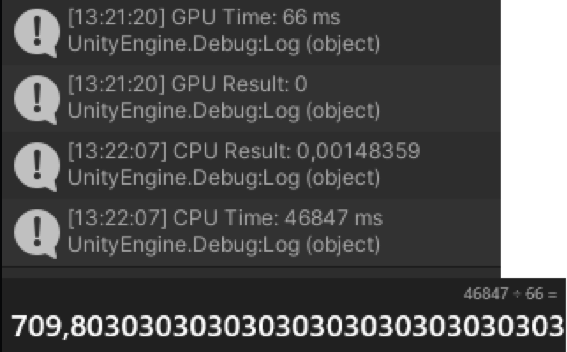
In these test results, the formidable capabilities of the GPU become evident. Given the complexity of the calculation, the CPU struggles and requires a substantial 45 seconds to complete the computation. In stark contrast, the GPU exhibits remarkable efficiency, finishing the task in a mere 66 milliseconds—nearly 710 times faster. These results underscore the significant advantages of leveraging GPU processing power for such intensive operations, yielding highly favorable outcomes.
Implementation
Problems of data transfer
Now that I tested the functionality of Compute shading it was time to put it into the project. This had some problems with it the first problem i encounters was the problem of information transfer between the CPU and GPU. Because i calculated the perlin noise on the CPU first and needed the information on the CPU the tranfser delay was nothing because it was already there, but if you want to transfer data between the CPU and the GPU you dont have this luxery. It takes a little bit of time to send the information from the CPU to the GPU. in the next image you can see how it works. the information is a bit exajurated for the wait time but it gives a good example

Here, you can observe that sending information from the CPU to the GPU takes a minimum of 2 seconds, as the data must traverse through the connection tunnel.
Now that we’ve identified a limitation with the GPU, it’s imperative to address this issue. In the current code, I sequentially inquire about the value of each cube within a chunk, which is highly inefficient. With approximately 4,000,000 cubes to process, it would theoretically take at least 8,000,000 seconds, equivalent to a little over 92 days. Although, in practice, the CPU-to-GPU data transfer only takes about 1 millisecond, it would still require 2.2 hours if each calculation was performed sequentially. This inefficiency prompts the need for a more optimized approach to enhance overall performance.
To address this issue, we need to send the entire list at once instead of each value separately. This approach ensures that the data traverses the connection tunnel only once for sending and receiving, resulting in a minimal 2 milliseconds of delay. In contrast, if we were to handle each value in the list separately, it would require 2.2 hours for the entire process due to the cumulative delay for each transfer.

Here, you can observe that we transmit the entire position list in a single transfer, leveraging the GPU’s parallel processing power to rapidly compute all the values. The calculated values are then compiled into a list and returned. This streamlined approach ensures that the data only needs to traverse the connection tunnel twice, significantly reducing the overhead compared to the 8,000,000 separate transfers in the previous inefficient method.
Here, you can observe the code implementation. In the following code snippet, I initiate the creation of a list encompassing all the positions where terrain is intended to be. This step is crucial as it allows for the subsequent transmission of the entire list to the GPU. This approach ensures that the GPU can process the entire list collectively, rather than addressing one value at a time.
    public static void SetTerrainHeight(int x, int y, int z)
    {
        reusableVector.Set(x - 2, y, z - 2);

        float xCoord = reusableVector.x * perlinScale;
        float yCoord = reusableVector.y * (perlinScale / 2f * 1.5f + 1 / (reusableVector.y + 1));
        float zCoord = reusableVector.z * perlinScale;

        // Store the position for later batch processing
        Vector3 position = new Vector3(xCoord, yCoord, zCoord);
        positionsList.Add(position); // Return 0 for now, update based on the terrain map
    }
In this section, you’ll observe that after obtaining all the positions where elements are intended to be, the next step involves computing all the corresponding values. To achieve this, the list of positions, along with the desired terrain scale, is sent to the GPU. Once the GPU completes the calculation, a refined list of values is obtained. This list is then returned to the main script, allowing for the retrieval of each value directly from the list. Importantly, this approach eliminates the need for CPU-based calculations, enhancing overall efficiency.
    public static float[] ProcessTerrainBatch()
    {
        // Use ComputeValues for batch processing

        float[] noiseValues = ComputeValues(perlinScale, positionsList.ToArray(), 0, 0, 0);
        positionsList.Clear();
        return noiseValues;

    }
Conclusion
I am quite pleased with the progress made this week. The compute shader functions exceptionally well, resolving previous issues with terrain calculations. While this aspect is now robust, there remain other challenges to address. For instance, optimizing mesh combination to further enhance performance and addressing terrain misalignment resulting from the GPU’s distinct calculation approach compared to the CPU.
Although the terrain currently appears slightly distorted, the underlying structure is discernible. Implementing the compute shader has significantly improved loading times, reducing it from over a minute to just a few seconds, as evident in the video clip. The terrain loading process is notably smoother, yet further optimization can be achieved by incorporating mesh combination in the upcoming iteration.
Looking ahead, my focus for the next iteration will be on refining mesh combination to address a slight lag spike stemming from the extensive mesh calculations. Additionally, efforts will be directed towards seamlessly reconstructing the terrain to eliminate any visible seams or cuts. These refinements aim to enhance overall performance and provide a more visually cohesive and immersive experience.
Iteration 4 – Repairs and Biomes
In this iteration, I am focusing on repairing the landscape to eliminate seams, as highlighted in the conclusion of the previous iteration. Although the terrain loads quickly and is visually acceptable, I aimed to enhance the landscape by addressing seam-related issues and making it more engaging. Currently, the landscape only features one type of biome that the game designer can determine, but I desired to incorporate various biomes throughout the landscape. This led me to delve deeper into creating biomes and fixing the broken landscape.
Identifying the problems.
Before i can make the landscape pretty with biomes i first have to fix the problem of the seems trough the landscape. These seems appeared after implementing the Compute shader. This made me think that the problem may lie in the calculation or how the GPU calculates the values. because in the previous test you can see that the GPU and CPU have a slight difference in the result value. You can also see this in the following picture.

Here you can see that the CPU and GPU have a tiny difference in result but if you have a slight difference almost 4.000.000 times it will eventually make a big difference.
This let me to the conclusion that it must be how the GPU calculates the result because the calculation was the exact same. Because of this i knew where i should look for the problem of the seems.
Solving the seems
Now that the problem is identified, it is time to verify if this is indeed the issue by attempting to resolve it and examining the results. When analyzing the outcomes from both the GPU and the CPU, I observed that the values were relatively small. This prompted me to investigate the issue further online.
According to Unity[12], the problem might stem from a floating-point error. Compute shaders, being limited by finite bits for calculations, can encounter precision issues. The concern is that the accuracy of calculations may be compromised. Therefore, it becomes crucial to scale up the values, ensuring that on a larger scale, the minor inaccuracies won’t significantly impact GPU calculations.
Now that we have this new information it is time to put it to the test.

In this section of the code, you can observe that when calculating the final result, I multiply it by an extremely large number—specifically, 1 followed by 38 zeros. This choice stems from the issue we recently encountered, where the values were not accurate on smaller scales. By using such a large multiplier and later scaling it down on the CPU, we aim to mitigate any potential problems.
The specific number we multiply with is 1.000,000.000.000.000.000.000.000.000.000.000.000.00
Now that we have a possible solution it was time to look at the game and see if the problem of the seems is solved.
Now, if you take a look, you’ll notice the seams are gone, and those pesky tiny value issues are fixed. The terrain now smoothly connects from one chunk to the next, with no hiccups in between. The changes in the code not only made chunks look better by getting rid of those seams but also ensured a nice, continuous flow between each chunk, making the whole terrain generation process much smoother.
Biome Generation
Now that the seems are fixed it is time for difference in biomes. I want to create biomes because it was getting kind of boring looking at kind of the same terrain all the time. If we look at subnautica for example you can see lots of different types of terrain. In the pixures below you can see some different biomes or terrain types from the game subnautica.


Here, you can observe the diversity in the landscape; it’s not a monotonous repetition. That’s precisely why I aimed to introduce biomes. While the terrain can stretch endlessly, it was becoming a bit predictable, featuring the same type of cave repeatedly. I envisioned having variations, like expansive open caves, uniquely shaped terrains, small cozy caves, or elongated worm-like structures. This motivated me to incorporate biomes into the terrain. With a clear plan in mind, the next step was delving into research to figure out the best approach.
from making my own terrain i knew that i had to do something with the “scale” of the terrain. the scale determinants how open the caves are or how junbeld they are the lower the value the bigger the caves and the higher the value the tinyer the caves. This is where i had to start.
    float basePerlinScale = 0.05f;

        // Calculate the adjustment based on the index within the chunk
        float chunkAdjustment = (index-1) / chunkSize;

    float xAdjustment = Mathf.Sin((x + chunkAdjustment) / 100) * 0.05f;
    float zAdjustment = Mathf.Cos((z + chunkAdjustment) / 100) * 0.05f;


        // Calculate the final perlin scale, clamped within a range
        perlinScale = Mathf.Clamp(basePerlinScale + xAdjustment + zAdjustment, 0.03f, 0.08f);

    float xCoord = reusableVector.x * perlinScale;
    float yCoord = reusableVector.y * perlinScale;
    float zCoord = reusableVector.z * perlinScale;
In the code, you can observe that I modify the perlinScale using the x and z world position of the vertex. This approach yields a dynamic landscape that transforms as you navigate through it. To ensure smoother transitions and create larger biomes, I divide the result by 100. Opting for the Sin and Cos functions was a deliberate choice. not only do they provide predictable outcomes, but they also offer a visually pleasing effect in my opinion.
After determining the necessary values, I applied clamping between 0.03 for larger caves and 0.08 for smaller caves. This precaution prevents values from becoming excessively large or negative, ensuring that players can navigate the landscape smoothly. Maintaining a balanced range of values is essential for an optimal gaming experience, preventing any issues where the player might struggle to traverse the terrain, ultimately contributing to an improved overall gaming experience.
Now that we change the code and know why we changed it we can look at the result.
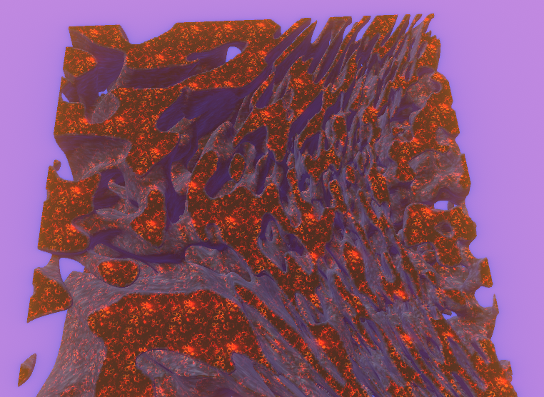
Here you can see the change in biomes. from a top down perspective.
Here, you can observe the player transitioning from the default cave system, characterized by a perlinScale value of 0.05, to a larger, more expansive cave system with a perlinScale of 0.03. The noticeable change in terrain as the player moves in different directions reflects the successful implementation of the biome system. I’m quite pleased with how it has turned out.
However, with the biomes functioning seamlessly and showcasing various cave types, the next step involves giving each biome its distinctive feel and appearance. To achieve this, I started by working on changing the textures.
Initially, I created a texture with three distinct parts, introducing some variation between the biomes. Following a Minecraft-inspired approach, I aimed to develop a texture atlas specifically tailored for the textures of my biomes.

Here, you can observe the various textures I intend to use for the different biomes. If I decide to incorporate more textures in the future, I can simply add them alongside these three. However, for the present, three textures will suffice.
Now that i have some texture i wanted to try it out just by slapping it onto the material and see how it looks. well the result was quite interesting and predictable.

Here you can see that it just loops trough the textures witch is good but not at this close of a range. The next task was to only get 1/3 of this texture and show that for some period of x position. and after that show the next 1/3 of the texture.
I attempted various approaches, but unfortunately, I couldn’t figure it out independently. After seeking assistance from the entire group of people working on shaders, I was only able to achieve 1/3 of the texture using the following code:

Here you see the calculation of getting only 1/3 of the texture and then looping that.
Here you can see the transition from one texture to the next when going over a threshold.
With the foundation for texturing in place and the landscape looking quite pleasing in my opinion, it’s now time to introduce some effects to enhance its overall appeal.
Look and Feel
It is time to add some effects and make it really a underwater cave system. For creating this effect i used fog and post processing to create the look and feel i wanted. I used bloom for highlighting the nice part in the textures and used fog to hide the loading chunks.
Here you can see the result from adding the post processing and the fog for the extra look and feel.
Conclusion
In short, I believe that in this iteration, the landscape truly came to life with all the changes. It performs quite well and almost looks the way I envision it. The atmosphere it creates gives off a fantastic underwater horror vibe, reminiscent of what Subnautica achieved back in the day. I’m genuinely pleased with the product and its current state.
Looking ahead to the next and final iteration, there’s still a need for some performance enhancements, and the project is nearing its ultimate form. The upcoming iteration will primarily focus on polishing, including further boosting performance to enhance transitions even more and bringing the entire environment to life.
Iteration 5 – Finalize
Now that the landscape has no broken parts and the water effect is in place, it is time to finalize the project. To achieve completion, I required several elements, including:
- Water Shader
- Sound
- Particles
- Gameplay
- Plants
- Biome Detection
- Fish
I must emphasize that this project centers on terrain and terrain generation. Elements such as gameplay, aesthetics, biome textures, and plants are designed to enhance the overall terrain experience. If something appears less polished, it’s not intentional but a result of the terrain being the primary focus. Due to time constraints and priorities, other aspects received less attention. With that clarification, let’s continue.
Water Shader
To make the feel of being in water really shine, I wanted to add a water shader. This was because now you can go through the caves with the fog and kind of feel that you are in water, but really diving into water just makes it feel like you are really in the water.
To create this shader, I referred to the tutorial by Freedom Coding[13]. It greatly assisted me in crafting the water shader, as it was a straightforward tutorial. All I had to do was follow the instructions and make some adjustments to ensure compatibility with my terrain. There isn’t much to showcase except for the adjustments and the end result. For the adjustment, I simply created a small script that positions the water at the desired height, nearly at the top. That was the only change I needed to make.

Here is the final result of the water shader. It integrates seamlessly with my terrain and presents a highly realistic appearance.
Sound & particles
The terrain already looks very nice, but there was something missing—it was awfully quiet. That’s when I knew that the game needed sounds, like underwater breathing and other ambient sounds, to bring it to life.
To address this, I began by creating a small script that utilizes multiple audio sources to play audio. The script searches for an audio source that is currently not playing anything. If the audio source is available, it selects one of the requested clips and plays it on that audio source. You can see the code for this in the picture below.

Here you can see that i request a drowning sound.
After that, I still needed some logic to call this function, so I implemented a timer to play the sounds. This led me to create a GameManager, from which I could initiate and control the playing of sounds.

Here you can see that i just make a timer for timing when to play the audio.
So now that we can play some sounds lets hear those sounds. caution it might be loud.
As you can see i also added some breathing particles to show that the person is exhaling breath. these bubbles also go upwards to show the player where up is if they get lost.
Gameplay
Now that the player has some sounds to base the current state of the player on it is time to put it in practice with game play. for the game play i wanted to creating a sort off seeking game wheer you need to find parts to build a beacon so you can ask for help. but to make this you first need to find the parts. These parts will of course on the bottom or somewhere near that vicinity so the player must dive down.
To challenge the player i created a oxygen meter so that the player could only stay underwater for a set amount of time before needing to go up. this is 30 seconds for now but will later be changed. to also make it a bit harder for the player and really sell the horror vibe of my terrain i played around a bit with the post processing values and light settings to make the following result in the video below
In this video, you can observe that it gets darker the further down the player goes. Additionally, the oxygen meter gradually decreases over 30 seconds. If it depletes completely, the health meter will start decreasing, accompanied by the drowning sounds from the audio in the video before this one.
Plants
In the previous video you could already see some plants but the question is how are they generated?
To make the biomes come to life we can add well life so that is why i made some plants. To see how these plants are generated we first have to look into how the terrain is generated.
When making the terrain we new that every vertex had a value to see what face should be connected to it. this is the part we need to figure out where to put the plants. when we get the value of the vertex we can see how the face is turned and then place a plant when the face is facing upwards

Here you can see that i put the values of the vertex in a list so i can access it in another script.

In this script i acces the values and spawn something if the faces are facing upwards or dont have a angle
Now that we know how and where to place plants lets first test it with cubes. the following image shows where the plants will be spawned but instead of plants there are cubes.

Here you can see that if the angle is very steep it should spawn plants or coral based on what i decide.
The only thing we need to do is to change the test objects to plants and then we have the result of the previous video.

Here you can see a image if the plants on the bottom of the world
Biome detection
To identify the various biomes present within the procedurally generated world, I employed the same calculation as the one used for texture generation. This calculation follows the texture and checks for changes in values. When the value transitions, such as from 0 to 1, it signifies a new biome. This information is then utilized to spawn specific elements corresponding to each biome. In the two photos above, you can observe, for instance, that in the lava biome, cubes can be spawned, while in the other picture, the player is in a different biome where plants can grow.
Fish
To spawn fish we use biome detection as well as the plant spawning. We can use the combination of these 2 to spawn certain fish types in certain biomes. This is because we can detect the biome with the previous biome detection and say we want for example a shark. to spawn the shark we use the plant spawning. Because the plants can only spawn in or on the rocks the only place left is outside the rock in the water.

Here you can see a representation of where all the plants can spawn. these places are shown with the cubes. the area between the cubed area is the water where the player and the fish will swim.

In the image above you can see that we can invert the places where the plants can spawn and than we get the area of the water so where the fish will spawn.
Sources
Landscape
[1] Poly Coding,”Marching Cubes Part 1: Explaining marching cubes”,20-02-2022, https://polycoding.net/marching-cubes/part-1/
[2] Henrik Kniberg,”Reinventing Minecraft world generation”,09-05-2022,https://youtu.be/ob3VwY4JyzE?si=mzTmsH16eP4FdKlQ
[3] U. Technologies,”Unity – Scripting API: Mathf.PerlinNoise”, https://docs.unity3d.com/ScriptReference/Mathf.PerlinNoise.html,(accessed 27-9-2023)
[4] b3agz,”How to Make 7 Days to Die in Unity – 02 – D̶u̶a̶l̶ ̶C̶o̶n̶t̶o̶u̶r̶i̶n̶g̶ (Smooth Terrain!)”,21-11-2019,https://www.youtube.com/watch?v=PgZDp5Oih38&t=335s
[5] Brackeys,”GENERATING TERRAIN in Unity – Procedural Generation Tutorial”,24-5-2017, https://www.youtube.com/watch?v=vFvwyu_ZKfU
[6] b3agz, “How to Make 7 Days to Die in Unity – 04 – Chunks”,20-2-2020,https://www.youtube.com/watch?v=5xYJJHWWCZU&t=219s
Texturing
[7] b3agz, “How to Make 7 Days to Die in Unity – 03 – Triplanar Texturing”,10-12-2019,https://www.youtube.com/watch?v=5xYJJHWWCZU&t=219s
Compute Shading
[8] Game Dev Guide”Getting Started with Compute Shaders in Unity”,31-12-2020,https://www.youtube.com/watch?v=BrZ4pWwkpto&t=549s
[9] Will Hess,”The POWER of COMPUTE SHADERS!!!”,24-11-2021,https://www.youtube.com/watch?v=E9wwi-F3gMw
[10] Arsiliath,”Intro to Compute Shaders”,14-2-2020,https://www.youtube.com/watch?v=V-yqiLyU27U&t=303s
[11] World of Zero,”Getting Started With Compute Shaders in Unity”,27-4-2017,https://www.youtube.com/watch?v=4Wh8GRrz7WA&list=PLraRC59GS-2pxlRKuzEvb0jqXgctaLFMh
[12] U. Technologies,”Unity – Manual:SL-DataTypesAndPrecision”,https://docs.unity3d.com/Manual/SL-DataTypesAndPrecision.html,(accessed 25-10-2023).
Shaders
[13] Freedom Coding”Unity 3D Water Shader – HLSL Tutorial”,28-10-2023,https://www.youtube.com/watch?v=wcGT_jji5xQ
