

I have always had an interest in certain mathematical abstract ideas. Things like fractals and multi-dimensional objects. This blog will talk about several ways to implement the creation and rendering of 4D objects, in a roughly chronological order.
The end product should provide a way to visualise a 4th dimensional objects inside unity. There should also be a way to create said 4D objects, and place them logically in a small world. These objects can include: Terrain, basic objects like a hypersphere, hypercube, but also a combination of these objects to create a more complex idea. During the project it turned out that while it is possible to combine these objects, this is quite hard to do so and this didn’t end up being in the scope of the project. The end result is a 4D dice simulation, which would allow a user to roll several dice
The basics of 4D
To get started I had to learn some of the basics. These will be explained very briefly here, according to a great set of blogposts by Alan Zucconi(1, 2, 3).
4D Space
A 4D object has 4 spatial dimensions instead of our normal 3 dimensions. This means an object has an x, y, z and w coordinate.
What Does a 4D Object Look Like?
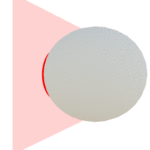
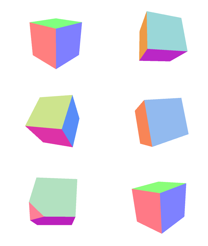
Visualizing a 4D object can be challenging. One way to visualise a 4D object would be to create 3D “slices” of a 4D object, much like you can create 2D slices out of a 3D object (a great real-world example of this is MRI). “A 4D sphere would appear as a “traditional” 3D sphere, suddenly growing and shrinking out of existence.”
Shadows of 4D Objects
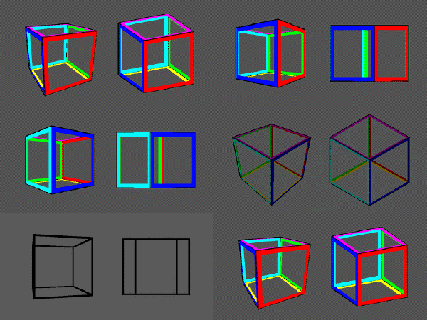
The aforementioned way of visualising a 4D object is called the cross-section projection. There are two more projections which are worth talking about: The perspective projection and the orthogonal projection(3). These offer a bit more insight in what is actually happening in the fourth dimension, and are fairly popular for depicting 4D objects. They essentially “squish” the fourth dimension into the third dimension, modifying the actual 3D coordinate depending on the W component. Note that while one cube seems smaller, they are actually the same size. In fact, all edges in the gif below are the same size!
Rotations in 4D
Just like we can rotate objects in 3D space, we can perform rotations in 4D. We often say “rotate something around an axis”. This would lead you to believe that you can rotate around one axis for every dimension. This works in 3D, but breaks down in 4D and even in 2D: You can only rotate around one axis, while there are two dimensions. Instead of rotating around an axis, it is easier to visualise a rotation as being around a plane, where that plane stays stationary. We then get six possible rotations: XY, XZ, YZ as the real rotations and XW, YW, ZW as the rotations involving the fourth dimension.
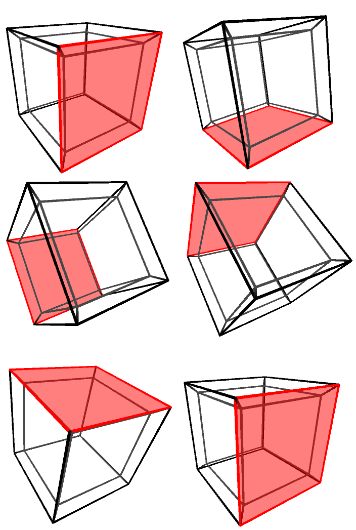
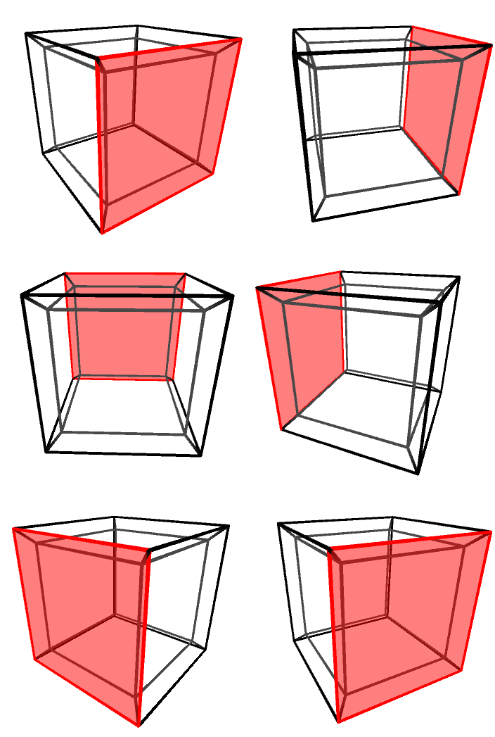
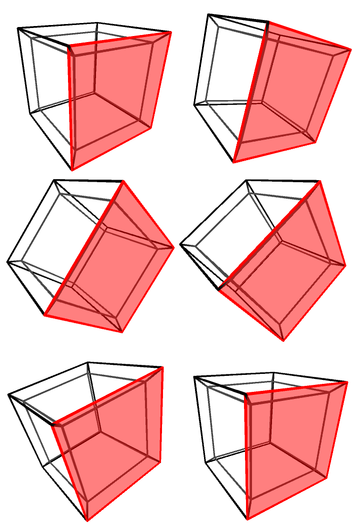
Hyperrotations
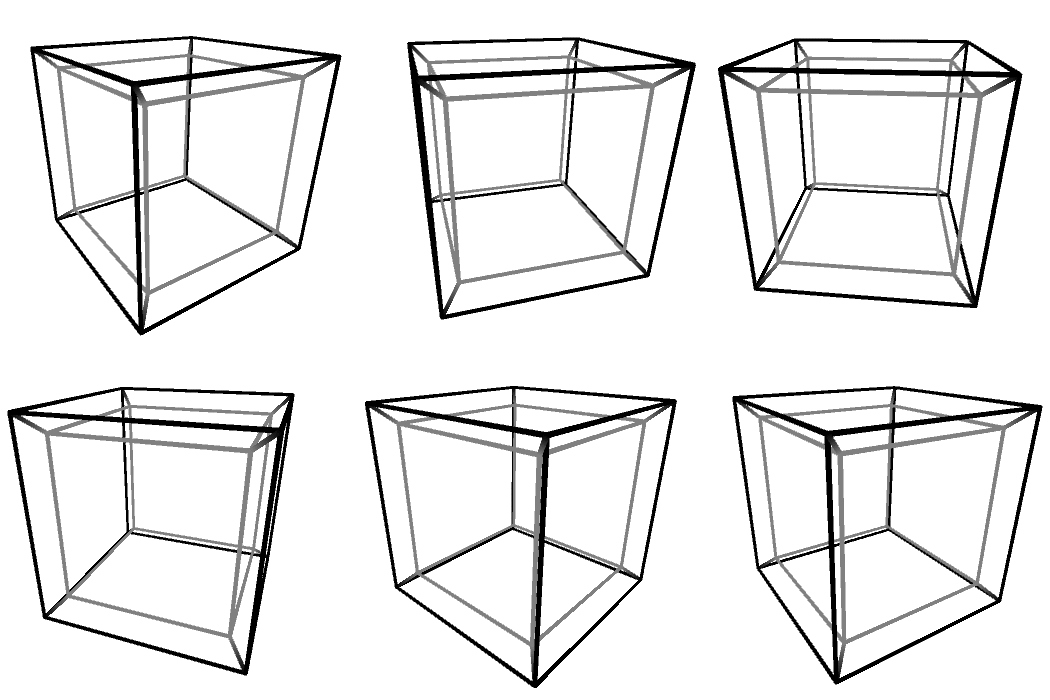
A rotation involving a 4D coordinate is called a hyperrotation. These produce a weird behaviour in their orthogonal projection: the edges seem to change in length, and the cubes seem to be flipped inside out in some weird way, as seen below.
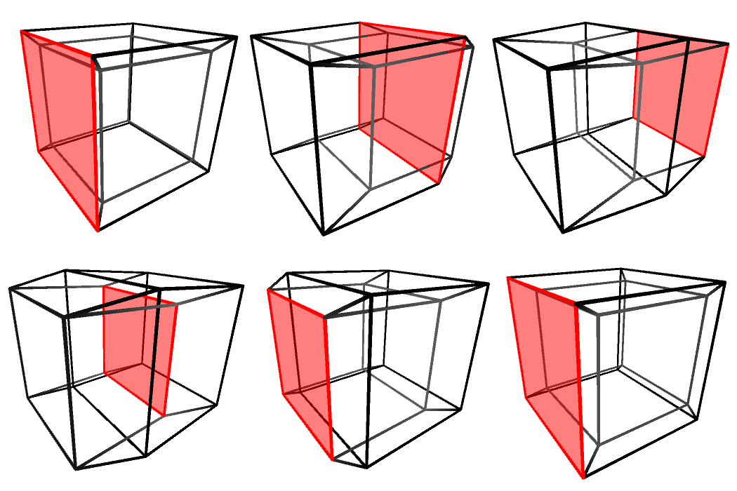
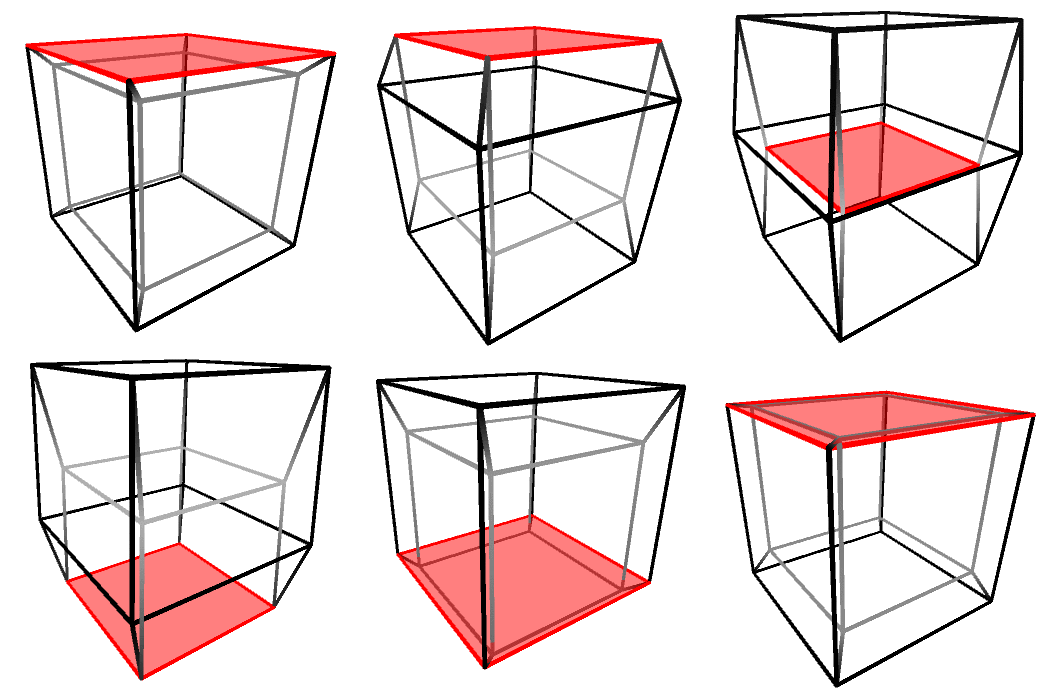
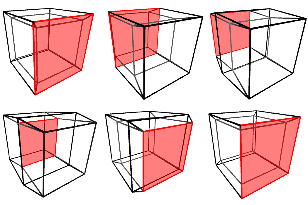
It is important to remember that the tesseract shown above is not really being flipped. It looks like that because we cannot perceive “depth” in four dimensions. Rotations in 4D do not deform 4D objects, in the same way rotations in 3D do not deform 3D objects.
Alan Zucconi
Simple 4D Objects
Creating 4D objects might sound complex, but there are relatively simple ones to start with. Two common examples are:
- Hypercube: Imagine a 4D cube with its four spatial dimensions.
- Hypersphere: Think of this as a 4D sphere, adding that elusive fourth dimension to the familiar sphere.Exploring these objects can provide valuable insights into the fascinating world of four-dimensional space.
Implementation in unity
To implement these features into unity, I followed the next part of the blog posts by Alan Zucconi(4). Zucconi actually made an implementation of 4D geometry in unity himself.
I also followed the basic structure Zucconi provided in his tutorial for scripts:
- A Mesh4D
- A Transform4D
- A MeshRenderer4D
- A MeshWireframeRenderer
More information about the classes can be found in Zucconi’s blog(4)
Mesh4D
A Mesh4D keeps track of a few attributes of a 4D mesh. As you would expect it keeps track of the relevant vertices, except these vertices are a Vector4 instead of a Vector3. According to Alan, it is also useful to keep track of which vertices are connected, so a struct Edges is added, which contains two indices of connected vertices.
For now I hardcoded a hypercube in the Mesh4D, to be able to implement a visualisation. This was done by manually adding the 16 vertices and 32 edges. This produces a hypercube, although it wasn’t possible to visualise this yet.
Transform4D
The transform4D was a bit harder to actually implement. While Zucconi generously provides code snippets for most of the work it is supposed to do, not all of his code immediately works and it is often ambiguous where the code is actually supposed to go. It provided a really valuable resource though, where the order of what should be happening was quite clear, and after puzzling a bit, I managed to port over most of Zucconi’s code.
The transform has a position, a scale and a rotation. The position and scale are a Vector4. The rotation has a new datatype: a struct, Euler4. This consists of six floats, one for each of the rotation planes.
The transform also has access to the mesh itself and a copy of the vertices. It modifies this copy to apply the scale, rotation and position.
A new topic for me was a rotation matrix. I used another tutorial by Alan Zucconi(5) which explains how rotation matrices work in 2D, and in 3D. If you ever worked with rotation matrices before you might have noticed that you use a 4×4 matrix for 3D manipulation. You can use a 4×4 matrix to apply position, scale and rotation all at the same time. To make it easier I am using a 4×4 matrix for rotation in 4 dimensions, and I apply the position and scaling separately.
It is also responsible for calling the current renderer, be it the normal or the wireframe renderer.
MeshRenderer4D
The third article by Zucconi(2) goes into detail about rendering a cross-section projection of the 4D object. Essentially you construct the 3D object that resides at W=0. You do this by iterating over the edges, seeing if they cross W=0, and finding the middle point between them. You then create a vertex at those positions. The resulting set of vertices will form the 3D object.
This intersection algorithm was implemented almost exactly as described in the blog post(3), with the exception of the list used being a Vector3 instead of a Vector4, because it contains the resulting 3D vertices where W is equal to 0.
public Mesh Intersect(Vector4[] vertices, Mesh4D.Edge[] edges)
    {
        // Calculates the intersections
        List<Vector3> vert3d = new List<Vector3>();
        foreach (Mesh4D.Edge edge in edges)
            Intersection
            (
                vert3d,
                vertices[edge.Index0],
                vertices[edge.Index1]
            );

        // Not enough intersection points!
        if (vert3d.Count < 3)
            return null;

        // Creates and returns the mesh
        return CreateMesh(vert3d);
    }
The article also talks about the triangles: it is quite complex to generate those on the fly. You can however generate them a bit more easily if the shape is convex. The article listed a library that does this, and I used this library too.
MeshWireFrameRenderer4D
The structure Zucconi used also had a wireframe renderer. He didn’t provide any code to it though, and I ended up making this one myself.
This renderer applies the orthographic projection, and scales the W dimension according to the formula nw, where n is any positive integer. This squishes the parts of the object that reside in the w dimension into the three spatial dimensions we’re used to.
Vector3 start = new Vector3(
  vertices[edge.Index0].x,
  vertices[edge.Index0].y,
  vertices[edge.Index0].z)
start *= Mathf.Pow(factor, vertices[edge.Index0].w);

Vector3 end = new Vector3(
  vertices[edge.Index1].x,
  vertices[edge.Index1].y,
  vertices[edge.Index1].z)
end * Mathf.Pow(factor, vertices[edge.Index1].w);

EdgeGameobjects[edgeIndex].transform.position = start;
EdgeGameobjects[edgeIndex].transform.LookAt(end, Vector3.up);

// Scale the cylinder between the two points
float distance = Vector3.Distance(start, end);
EdgeGameobjects[edgeIndex].transform.localScale = new Vector3(1, 1, distance);
Generalising the Mesh4D
To create multiple different shapes it would be nice to be able to choose from a multitude of shapes – a more spiky shape, a hypersphere, etc. I decided that it would be useful to be able to generate multiple convex regular polychora, the 4D equivalent of the regular polyhedra. To do this I needed to do two things: generate the vertices the edges of this polychoron.
Vertex generation
The vertices can be generated by creating all possible permutations and changes of sign of a seed vector(5). For example, the seed vector for a hypercube is (1, 1, 1, 1). This results in the 16 changes of sign possible. A 16-cell is generated by generating all permutations and changes of sign of (1, 0, 0, 0). This results in (±1, 0, 0, 0), (0, ±1, 0, 0), (0, 0, ±1, 0), (0, 0, 0, ±1).
One more detail is that some polychora required even permutations(6). To get a permutation of a set, like (1,2,3,4) you can swap two items, like (1,2) to get (2,1,3,4). If the amount of swaps is even, the permutation is even. This is called the parity. This parity is important for some shapes that will appear later.
This was implemented by iteratively looking for the different combinations. I based my function off a StackOverflow thread(7). The basic method resulting from this looked like this:
private static List<Vector4> DoPermute(float[] nums, List<Vector4> list, int start = 0)
{
    if (start == nums.Length - 1)
    {
        // We have one of our possible n! solutions,
        // add it to the list.
        list.Add(new(nums[0], nums[1], nums[2], nums[3]));
    }
    else
    {
        for (var i = start; i < nums.Length; i++)
        {
            Swap(ref nums[start], ref nums[i]);
            DoPermute(nums, list, parity, start + 1);
            Swap(ref nums[start], ref nums[i]);
        }
    }

    return list;
}

private static void Swap(ref float a, ref float b)
{
    (a, b) = (b, a);
}
To get all the sign changes I executed the DoPermute function once for every sign combination and discarded doubles.
Even permutations
While the theory of even permutations was quite clear to me, the implementation turned out to have a few important details. My first idea was to keep track of the amount of swaps in the method itself. I couldn’t get this to work. I tried a boolean function to check if the permutation was even. This also seemed to have problems. This took a lot of debugging and trial and error, and eventually I found out that the real problem was the order in which the sign changes and the permutation itself happened.
For this to make sense we need to look at the method for calculating if an array is an even or an odd permutation:
public static bool IsEvenPermutation(float[] arr)
{
    int count = 0;
    for (int i = 0; i < arr.Length; i++)
    {
        for (int j = i + 1; j < arr.Length; j++)
        {
            if (arr[i] > arr[j])
            {
                count++;
            }
        }
    }
    return count % 2 == 0;
}
For example: if we have the set {1, 2} and we check if it is even, it checks that 1 > 2, which is false. The count stays at 0. {2,1} is an odd permutation, because we swapped once, so count would be one. This also works with larger lists.
If we however change the sign of a number first we could get {1, -2}. This permutation hasn’t been swapped but would return as an odd permutation, as 1 > -2 returns true, therefore count is equal to 1.
After looking at the resulting vertices of another implementation(8) of the polychora generation I noticed that this order had to be reversed – first all permutations (or in the case of even permutations only those permutations) of the base seed were taken, and then the sign changes were implemented.
List<Vector4> vertices = new();

// Get all permutations of a seed
Vector4[] permutation = Permute(vertex, parity);

// Then add all sign variations for each permutation
foreach (Vector4 perm in permutation)
{
    for (int x = 0; x < 2; x++)
    {
        for (int y = 0; y < 2; y++)
        {
            for (int z = 0; z < 2; z++)
            {
                for (int w = 0; w < 2; w++)
                {
                    Vector4 signPermutation = new Vector4(
                        perm.x * (x == 0 ? 1 : -1),
                        perm.y * (y == 0 ? 1 : -1),
                        perm.z * (z == 0 ? 1 : -1),
                        perm.w * (w == 0 ? 1 : -1));
                    vertices.Add(signPermutation);
                }
            }
        }
    }
}

// Remove duplicate vertices
for (int i = 0; i < vertices.Count; i++)
{
    for (int j = i + 1; j < vertices.Count; j++)
    {
        if (vertices[i] == vertices[j])
        {
            vertices.RemoveAt(j);
            j--;
        }
    }
}
Results
After these issues were all fixed the resulting shapes looked like this.
Terrain
To continue with the possibilities of a 4D environment I decided to implement a 4D terrain generation system. To be able to get concave terrain with my current renderer I split this up into a grid of 4D objects. One drawback of doing it this way it requiring to use a 3D array of 4D objects. This terrain chunk generation worked by first generating the terrain vertices, then generating the edges.
Each chunk has 16 vertices:
for (int i = -1; i <= 1; i+=2)
{
  for (int j = -1; j <= 1; j+=2)
  {
    for (int k = -1; k <= 1; k+=2)
    {

      float y = yBase + noiseAmplitude * noise.snoise(
        new float3(
          (i + pos.x) / period,
          (j + pos.z) / period,
          k/period));
      vertices.Add(new Vector4(i, 0, j, k));
      vertices.Add(new Vector4(i, y, j, k));
    }
  }
}
The edges are then found by iteratively comparing at if the vertices. An edge gets added if:
- The two vertices are one grid unit away from each other in the x, z or w direction, and the Y is either zero or not zero. Due to noise the distances are unpredictable, this way we circumvent that.
- If they are the same Y coordinate. Again, this way we circumvent noise randomness.
// In a double loop through all vertices, comparing vertex i with vertex j
if((oneGridUnitAwayFromEachother && (bothYZero || bothYNotZero)) || sameXZW)
  edges.Add(new Edge(i, j));
Terrain(?)
Great, just create a grid of these terrain chunks and done!
Or so I thought, because a 20 by 20 grid crashed unity. It seemed that both the garbage collection and the scripts themself ate a lot of computing time. After a day of debugging, trying to optimise little code bits, and trying out different techniques it seemed that the main issue was just with my current implementation of the renderer. I also got sick at this point, and was out of the running for a good week. At this point I decided not to continue on this path, because it brought too many risks.
The alternative product: 4D dice
To be able to show off my project, I ended up deciding to pursue a 4D dice simulator. For this I needed a few things: a physics approximation, a way to read the result when the die has been rolled and a small tray. I decided to use the orthogonal projection for this, since it visualises the whole shape at once and makes for a weirder looking shape, with interesting interactions.
The tray
I decided to start easy and re-use the terrain to create the tray. The tray is now a small box with walls made of terrain chunks. Not too interesting, especially because no texturing exists for these 4D objects.
Reading a result
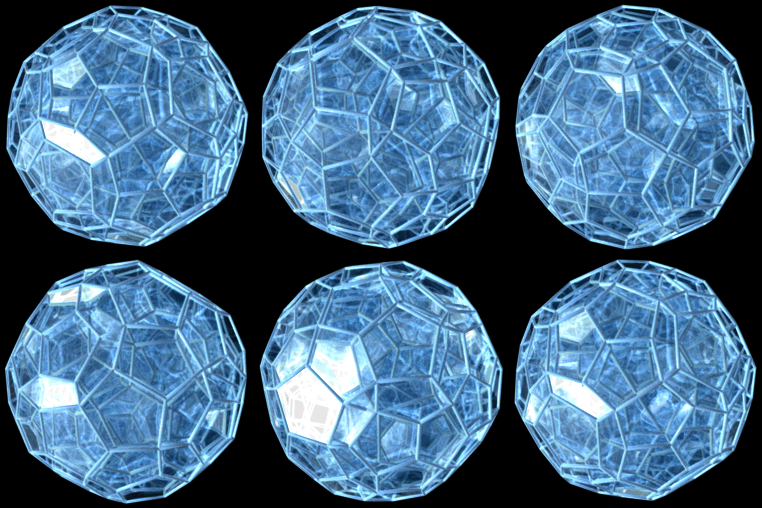
Reading a result has a fairly easy solution, although it is not the most satisfying solution. Typically, in 3D, you would use faces to generate a result. In 4D a logical step could be to use a cell instead, a 3D building block of the polychoron. Actually deciding on which cell would be on top in 4D space would be a monstrous task, so this idea was discarded. Articles as recent as 2001 have been written about the complexities with shapes like the 120-cell(10).
The simplest solution would be to check which vertex has the highest y coordinate and base the result on that, however this doesn’t quite feel satisfactory.
The final solution, which would be the nicest solution to have, would be to read a result from a plane. For this each plane has to be uniquely defined. A plane can be uniquely identified by a normal vector and one point. This can be achieved by looking at each set of edges with a common vertex, and adding it’s corresponding plane to a list if it’s not yet in that list. This still doesn’t give the plane any visual indication of the number it has rolled, but it at least encodes that information in the shape itself.
Or so was my idea. It turned out to be a huge hassle. I had to project the 4D hypersphere in a way to be able to read all the faces, and then make sure no faces were extra or missing.
The final code to get the edges was based on the way the MeshWireFrameRenderer4D works, except the projection is linearly projected into 3D space. Based on this it loops over the edges and adds all faces to an array:
public static Face[] GetPolychoronFaces(Vector3[] vertices, Mesh4D.Edge[] edges)
{
    List<Face> faces = new();

    for (int i = 0; i < edges.Length; i++)
    {
        for (int j = i + 1; j < edges.Length; j++)
        {
            // Check if the two edges share a vertex. If they dont, continue.
            int index00 = edges[i].Index0;
            int index10 = edges[i].Index1;
            int index01 = edges[j].Index0;
            int index11 = edges[j].Index1;

            int[] indices = {index00, index10, index01, index11};
            int[] uniqueIndices = indices.Distinct().ToArray();

            if (indices.Length == uniqueIndices.Length) continue;

            // Get the normal of the plane the two edges define
            Vector3 normal = Vector3.Cross(
              vertices[uniqueIndices[0]] - vertices[uniqueIndices[2]],
              vertices[uniqueIndices[1]] - vertices[uniqueIndices[2]]
            ).normalized;

            // Get the point on the plane
            Vector3 point = vertices[index00];

            Face newFace = new Face {
              Normal = normal,
              Center = point,
              Indices = new List<int>(5)
            };

            // Check if the face already exists
            bool exists = false;
            foreach (Face face in faces)
            {
                if (IsSamePlane(face, newFace))
                {
                    exists = true;

                    // Add the missing indices to the existing face
                    foreach (int index in uniqueIndices)
                    {
                        if (!face.Indices.Contains(index))
                        {
                            face.Indices.Add(index);
                        }
                    }

                    break;
                }
            }

            // If the face doesn't exist, add it
            if (!exists) faces.Add(newFace);
        }
    }

    return faces.ToArray();
}

private static bool IsSamePlane(Face face1, Face face2)
{
    // Check if the plane defined by the first face
    // is the same plane as the second face
    // This is the case if the normal is the same and the point is on the plane

    return (face1.Normal == face2.Normal || face1.Normal == -face2.Normal) &&
      IsPointOnPlane(face1.Center, face2.Center, face2.Normal);
}

private static bool IsPointOnPlane(Vector3 point, Vector3 planePoint, Vector3 planeNormal)
{
    // Calculate the vector from the plane point to the given point
    Vector3 vectorToPlane = point - planePoint;

    // Calculate the dot product of the vector
    // to the point and the plane's normal
    float dotProduct = Vector3.Dot(vectorToPlane, planeNormal);

    // Check if the dot product is close to zero (considering a small tolerance)
    float tolerance = 0.0001f;
    return Mathf.Abs(dotProduct) < tolerance;
}
Based on this I could calculate the center of each face, and get the highest center. This resulted in a fairly agreeable result, you could visually see that you should get that result.
Physics
Physics turned out to be the bane of my existence. I tried a lot of things – first, approximating a die path when the die was at a certain height. Then I tried using a lot of different combination between letting the a RigidBody control parts of the transform. This all ended up failing, either because the changing of the transform4D messed with the physics engine or because the unity transform has quaternions underlying them, which results in a different order of rotations being applied. Every fix I tried wasn’t working. This was unfortunate, but the best solution still uses the rigidbody – although only for collisions. The rest is a messy, hacky set of made up rules to create a rough dice effect:
- When a collision happens the angle is adjusted to the speed. Lower speed, more random angle change.
- Lower speed also means more reduction in speed. This way I hoped to achieve a “stopping” motion when the dice was slowing down.
- The angular velocity is emulated in a way, with the following code. The XY and YZ rotation planes are rotated to push the angle that collided up, and the other rotation planes are just randomly assigned.
private void BounceEmulation(Vector3 pos)
{
    Vector3 diff = pos - transform.position;

    angularVelocity.XY = diff.x * -angularVelocityModifier *
      Mathf.Abs(velocity.y);
    angularVelocity.YZ = diff.z * angularVelocityModifier *
      Mathf.Abs(velocity.y);

    angularVelocity.XZ = diff.x * angularVelocityModifier *
      Mathf.Abs(velocity.y);
    angularVelocity.XW = diff.y * angularVelocityModifier *
      Mathf.Abs(velocity.y);
    angularVelocity.YW = diff.y * angularVelocityModifier *
      Mathf.Abs(velocity.y);
    angularVelocity.ZW = diff.z * -angularVelocityModifier *
      Mathf.Abs(velocity.y);
}
Besides this, the approximated physics are similar to 3D physics. This results in an approximate dice throwing experience. Due to time constraints the number is only shown on the UI.
Conclusion and result
Based on these weeks of research and implementation I have experienced a lot of things. I have learned that some things do scale perfectly easy to 4D, while others suddenly become extremely hard. Overall this has certainly improved my ability to think abstractly about concepts in space. I learned a lot of things about 4D space, and about rendering in general (like how quaternions work! I think that’s pretty cool).
I am mostly satisfied with the product. I would like to give a visual indication to the player of what number they might be rolling, it is a little weird to just be told what you rolled.
Future iterations might implement that, improve on the environment and UI, and in general the polish could be a lot cleaner.
Sources
- Zucconi, A. (2023). Unity 4D #1: Understanding the fourth Dimension. Alan Zucconi. https://www.alanzucconi.com/2023/07/06/understanding-the-fourth-dimension/
- Zucconi, A. (2023). Unity 4D #2: Extending unity to 4D. Alan Zucconi. https://www.alanzucconi.com/2023/07/06/unity-3d-to-4d/
- Zucconi, A. (2023). Unity 4D #3: Rendering 4D objects. Alan Zucconi. https://www.alanzucconi.com/2023/07/06/rendering-4d-objects/
- 4th dimension projections: orthographic and stereographic projections. (n.d.). https://www.math.union.edu/~dpvc/math/4D/projections/welcome.html
- The regular polychora. (n.d.). https://www.qfbox.info/4d/regular
- Statistics – odd and even permutation. (n.d.). https://www.tutorialspoint.com/statistics/odd_and_even_permutation.htm
- Listing all permutations of a string/integer. (n.d.). Stack Overflow. https://stackoverflow.com/questions/756055/listing-all-permutations-of-a-string-integer
- Walczyk. (n.d.). polychora/include/polychora.h at master · mwalczyk/polychora. GitHub. https://github.com/mwalczyk/polychora/blob/master/include/polychora.h
- File:120-cell.gif – Wikimedia Commons. (2011, February 6). https://commons.wikimedia.org/wiki/File:120-cell.gif
- Stillwell, J. (2010). Mathematics and its history. In Undergraduate texts in mathematics. https://doi.org/10.1007/978-1-4419-6053-5
- Solution | Is it a plane? | Combining Vectors | Underground Mathematics. (n.d.). https://undergroundmathematics.org/combining-vectors/is-it-a-plane/solution

