

For this R&D project I wanted to recreate the crisp outlines from Unexplored 2 and the Halftone shading style from Hi-Fi Rush or Spiderverse movies. I chose to research this for 5 weeks, because it fits with my passion for cartoons and comics and the shader workshop piqued my interest for writing shaders and its capabilities.
Prior to this project I didn’t have any experience writing shaders aside from the bootcamp workshop. The workshop piqued my interest and I wanted to learn more about shaders and the myriad of techniques used to achieve various effects or stylizations. By learning all these techniques, I hope to become adept enough to be able to apply these techniques accordingly depending on the various factors (i.e. performance, theming) that involves in developing a game or product.
Table of Contents
- Outlines
- 1.1. Grayscaling Methods
- 1.1.1. Grayscaling with luminance
- 1.1.2. Depth Buffers
- 1.1.3. Normal Buffers
- 1.1.4. Depth + Normal Buffers
- 1.2 Edge Detection Algorithms
- 1.2.1. Laplacian
- 1.2.2. Sobel
- 1.2.3. Prewitt
- 1.2.4. Canny
- 1.2.5. Roberts Cross
- 1.3 Modifying the outlines
- 1.3.1. Adding Color
- 1.3.2. Adjusting thickness
- 1.4. Comparisons
- 1.5. The Outline Shader
- 1.1. Grayscaling Methods
- Toon Shading
- 2.1. Improving The Shader
- 2.2. Specular Lighting
- 2.3. Changing the Shadow Color
- Half-Toning
- 3.1. Shadows
- 3.2. Lighting
- 3.3. Mixing Halftones
- 3.4. Fixing Ellipses
- 3.5. Characters
- Final Result
- Conclusion
- For Further Studies
- Bibliography
1. Outlines
I started off with the outline shader. The first step was to draw the outlines on objects. In order to do that, I had to implement some form of edge detection in the shader script. While following this tutorial I came across some edge detection algorithms that could be used to determine discontinuities. I decided to put more research into multiple edge detection algorithms and the differences between them.
For these edge detection algorithms, there needed to be a way first to simplify the RGB values into a singular value that the algorithms can use to calculate with. There are multiple ways you can simplify the values for the algorithms. Often with image processing, people would greyscale the image before running the algorithms, but since we are working with 3D objects and rendered images, it would be useful to take a look at depth buffers and normal buffers. While testing these methods, I mostly used the Laplacian algorithm, which would be explained in the next part.
1.1. Grayscale Methods
1.1.1. Grayscaling with Luminance
In order to grayscale an object or image, you would need to calculate the relative luminance of a pixel’s color. The relative luminance is in simpler terms, what the perceived brightness is for humans, like how yellow light seems to be generally brighter than for example blue light. In order to calculate the relative luminance, you would need to use this formula.
**L =(r * 0.299) + (g * 0.587) + (b * 0.114)**With the grayscale filter applied, we could use the color changes between multiple objects and use an algorithm to draw a line right at these differences. The downside of this algorithm is that if two objects have the same color or hue, that no line would be drawn between these objects. After grayscaling the image, the Laplacian algorithm would be applied, which results into this.

In the tutorial, they use a step function, but this results in disconnected lines. I assume this has something to do with the depth and how the colors of a flat plane is rendered in 3D space, or that the lines are so thinly rendered, that it doesn’t reach the threshold given. So for now, I removed the step function.
The next step was to render the camera texture, which is done by adding the texture values to the calculated outlines, which results in this. Since the outlines are always white, I assume that the calculated outlines always result in a positive number. For now, I reversed the calculation, making it return a negative number which would result in these black outlines. This is something I’d like to improve on, as I want to be able to freely adjust the color of the outlines in my shader.


As mentioned earlier, the main problem with Grayscaling is when objects have the same color, lines would not be drawn, as you can see in the images below.


I think this may be remedied by adding another algorithm to determine edges, which is why the next method we will check is the depth buffer method. If I were to continue the grayscale method, I’d like to see how I can improve it further, since the objects seems to be bleeding through the outlines which does not look very nice.
1.1.2. Depth Buffers
Depth buffer is a screen filter that grayscales the screen based on the distance between the camera and the object. This works well with this project, since we are working with 3D objects inside the scene. Since it is more depended on depth instead of color, two objects having the same color wouldn’t pose a problem as mentioned in the grayscale method. To test that theory, we’ll check how this works in Unity.
For this part, I primarily followed this tutorial on adding depth buffers.
The depth texture is actually already given by unity, you just need to sample it in the shader. In the tutorial given, they’re calculating the screenspace and converting into UV coordinates, but I find that this is not needed if you render this shader via the camera, since the native UVs are the screen space UVs. It was only needed if you want to render the depth texture via an object inside worldspace.
Sampling the texture is show in the code below. As I said, the depth texture is already given by Unity. It’s a Sampler2D called _CameraDepthTexture. You can sample this texture using the macro SAMPLE_DEPTH_TEXTURE and decode it with Linear01Depth. You could also use LinearEyeDepth to decode the depth texture, but it gives a different output. According to this forum post, the difference between the two functions is quoted:
LinearEyeDepth takes the depth buffer value and converts it into world scaled view space depth. The original depth texture 0.0 will become the far plane distance value, and 1.0 will be the near clip plane. So now with the value you get from the linear eye depth function, 1 is a surface that is 1 unit from the camera’s pivot along the camera’s z axis. A value of 100 is 100 units, 200 is 200 units, you get the idea.
Linear01Depth mostly just makes the non-linear 1.0 to 0.0 range be a linear 0.0 to 1.0, so 0.5 really is half way between the camera and far plane.
-bgolus (2012)
Sampling the texture and making the camera render it would result in this.
sampler2D _CameraDepthTexture;
float depth = Linear01Depth(SAMPLE_DEPTH_TEXTURE(_CameraDepthTexture, i.uv));

Now all that is needed is to apply the edge detection algorithm, and reapplying the camera texture.


For this first attempt, I used the _CameraDepthTexture without decoding it. Slight differences could be seen between the two, whereas the lines using a depth buffer seem slightly crisper, but the grayscale can detect the edge of the platform. This must be because the platform has a slight gradient in the depth texture, as seen above, or maybe it’s the algorithm itself that is unable to calculate the edges inside the texture. Or perhaps it’s because using only the _CameraDepthTexture without decoding its values outputs a different image than the one above, meaning that the algorithm is working values that we do not expect.
So back to the drawing board, I wanted to use the decoded depth texture to calculate the outlines, and find that SAMPLE_DEPTH_TEXTURE uses a UV coordinate to sample the values. So by adjusting this UV values, I could get the neighboring pixels and use the Laplacian algorithm that I used in the previous method. So far, this drew the best outlines.


Compared to the previous two, this looks much nicer, but I find that the problem still occurs when it comes to objects overlapping. In the screenshot below, you could see the outlines not being drawn at the places where the objects overlap. I assume this is because the generated depth values are too similar, so the outlines aren’t drawn.
By reducing the far plane distance, the outlines are drawn between overlapping objects, probably because the depth values now have bigger differences between them, making it easier for the algorithm to detect the edges. I think aside from reducing the far plane, there should be another way adjust these depth values.


1.1.3. Normal Buffers
Another method for for edge detection is the normal buffer. This method uses the normal texture of the viewspace normals. This texture isn’t grayscaled like the other two methods, instead it looks like any other normal map that you come across when you’re working with 3D models. Since it’s a normal map, the values given are 3D vectors, meaning that we will have to simplify these values into one. You can do this by getting the dot product of the green vector and the red vector, which results in a single value scalar. We can use this value in the algorithms presented below.
Now the main problem I came across is that the tutorial that I was following is using the universal render pipeline, which would generate the normal texture and give it as a Sampler2D called _CameraNormalsTexture. My project is primarily using the built-in render pipeline, making it difficult to follow the tutorial, so I had to find another way to generate a normal texture. Unity does still give the view space normals in a texture, but this texture is encoded together with the depth values in a texture sample called _CameraDepthNormalsTexture. It is worthwhile to mention that this texture has both the depth values and normal values of the viewspace, so if you needed one or the other, you would have to separate the values. You could do that by using the function DecodeDepthNormal, which performs other decoding functions to get the depth values and the normal values out of the texture.
fixed4 normalTex = tex2D(_CameraDepthNormalsTexture, i.uv);
DecodeDepthNormal(normalTex, depthValue, normalValue);
float4 normalColor = fixed4(normalValue.rgb, 1);

I would also like to note that while testing, this shader only works in runtime, unlike the depth buffer.
Now that we have the normal values, we get the scalar value for each cell that we need for the kernel, and use the Laplacian algorithm to calculate the outlines. Now here comes the weird part.

That looks, really weird, and not what I expected. Taking one more look into the code and it seemed I miswrote a property, so fixing that and running the code again results in this:

That looks better! And the plus point of this is that it seems to get the edges on the front side of the cubes, something that the other methods could not detect so far. However, it doesn’t seem to find the plane in the background, and some lines are just barely visible. In order to remedy that, I added a threshold value to compare the calculated outline value to, and would set the value to 1 if it hits the threshold, and otherwise renders it 0.

Now we have those outlines drawn on the cube, but it seems it’s also drawing those lines on the spheres and capsules, something we don’t want. I assume it has something to do with the dot values generated for the texture. Going back to the code again and debugging it, I found that I was using fixed for all generated values, instead of a fixed4. This might mean that the normal values were not taken into account. So fixing that resulted into this:


Some improvement! Now the platform is taken into account, but it seems the artifacts are getting a different pattern.
Outputting the dot values shows this, which may be why there are weird patterns drawn onto the sphere and capsule.

I suspect that this may be the reason why there’s weird artifacts being rendered on the spherical objects. Perhaps the way to fix this, is by using another algorithm?
1.1.4 Depth + Normal Buffers
So what if we used the two methods together. They both have their up and downsides, so maybe they can cover each other’s weaknesses. So using the methods I’ve already used in the previous sections and combining the outputs, I hope to get a better result. Since the _CameraDepthNormalsTexture hold both depth and normal values, I separate the two values and calculate outlines with the two textures separately. It also seems that this depth value is already decoded, so no need to use Linear01Depth.
float oDepth = depthValue1 + depthValue2 + depthValue3 + depthValue4 - (4*depthValue0);
float oNormal = valueT + valueL + valueB + valueR - 4*valueC;
oDepth = oDepth > _DThreshold ? 1 : 0;
oNormal = oNormal > _NThreshold ? 1 : 0;
float outline = max(oDepth, oNormal);

1.2. Edge Detection Algorithms
From this point on, I’ll be primarily be using normal and depth buffers to test these algorithms with. Since we are working with 3D objects, I found that combining these two methods works best in a Unity scene. I also found that it produced the best outlines compared to the rest of the methods.
1.2.1. Laplacian
Laplacian is an edge detection algorithm that uses one image kernel. This algorithm only checks the direct sides of the center pixel, ignoring the corners. Since it only uses one kernel, the runtime complexity of the Laplacian is lower compared to the other algorithms.

Result:

1.2.2. Sobel
Sobel uses two image kernels, one that checks the vertical axis and the horizontal axis. After these two have been calculated, they’re combined together using the Pythagorean method.

Result:

1.2.3 Prewitt
Prewitt uses two image kernels, similar to the Sobel operators. The only difference is that it doesn’t add an emphasis to the center pixel. Similar to the Sobel method, the two results are combined together to determine the color difference. In order to compare this method with Sobel fairly, I gave it the same threshold values that the Sobel algorithm uses.

Result:

1.2.4. Canny
Canny is a more intensive edge detection algorithm, in the sense that it involves a lot of iterations compared to the other three algorithms. Usually, Canny uses Sobel kernels to calculate the edges, but in a lot of images, these edges are uneven and disconnected. Canny has extra steps to ensure more cleaner and even lines. After calculating the edges, the algorithm starts comparing the pixel strength with it’s directional neighbors. If the pixel value is the highest among it’s neighbors, it would be considered an edge pixel, otherwise it would be disregarded. This step is called non-maximum suppression. According to this article, what would usually happen is that the result would have choppy, disconnected lines, so it has another step where it will connect these lines. This is done with a method called Hysteresis Thresholding. Every pixel is iterated and compared to a high threshold and a low threshold. Pixels that hit the higher threshold, will be marked as edge pixels, as for pixels that have a value lower than the low threshold, will be disregarded. Pixels between the two thresholds will be considered as edge pixels if they happen to be connected to an edge pixel, or it will also be disregarded. After iterating through all the pixels, it should have crisp outlines.
Now the question begs, how does this work in Unity? Running three separate algorithms that iterates every pixel or texel on every draw call sounds very expensive, especially with bigger resolutions. While this method was not implemented in Unity itself, I think it was useful to research and may prove useful for further studies.
1.2.5. Roberts Cross
Another method I found while diving deep into edge detection and drawing outlines in games is the Roberts Cross algorithm. This algorithm works similarly to Sobel or Prewitt, except that the matrix it uses four pixels instead of 9. Roberts Cross takes subtracts the two pixel values within a kernel. The two kernels are then, similarly to Sobel and Prewitt, put into a Pythagorean formula to calculate the gradient value.

Result:

1.3 Modifying the Outlines
1.3.1. Adding Color
For now I multiply the color sample with the outlines, but this isn’t a very effective method as it doesn’t fully show color and black isn’t an option, so I had to find a different approach.
Instead, I check if the outline values are equal to 1, and if that’s true, that specific fragment will adopt the given _LineColor instead of the main texture. Now, it outputs the color right at the outlines, and gives off a wider range of values.
Result:
1.3.2. Adjusting Thickness
To adjust the thickness, I found out that one way to adjust it is by modifying the texelsize. So I multiplied the TexelSize, adjusting the displacements. This does indeed produce thicker outlines the bigger the value, but:
These outlines are kinda jarring, and very ugly. Furthermore, it seems to extend inward instead of outward. This may need further research, however I think this may be on the right track.
1.4. Comparisons
All algorithms aside from Laplacian seems to require a bit more work in order to finetune the outline output, also noting that Laplacian also needs some finetuning in order to make uniform lines, as you could see in the example above. Other than the Laplacian, they also could not draw all of the lines on the cube. Prewitt seems to produce less artifacts while also drawing less lines than Sobel. Roberts Cross produces thinner lines compared to the former two, but is quicker to draw unwanted lines compared to Laplacian. Every algorithm aside from Laplacian also seems to miss the platform underneath the objects. Both Sobel and Prewitt does produce thicker lines due to their bigger kernels.
How does this shader fare with more complex scenes? or characters? I took a low poly environment, a more high definition environment and a complex character model from the Unity Asset Store and applied all 4 shaders in the listed scenario’s.
Character Model


I feel that for these types of toon characters that a thicker outline shader like Prewitt or Sobel looks better than Laplacian.
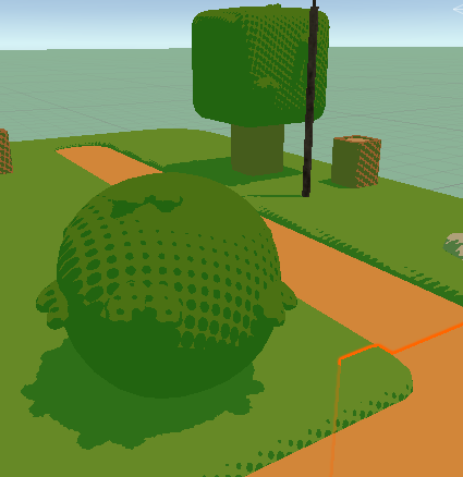
Lowpoly scene


For this scenario, I’d say that Robert’s Cross or Laplacian produces the nicest results, as both Sobel and Prewitt misses a lot of potential lines. However, ideally for such a low poly environment the outlines should only be drawn at certain colored segments (like the roads, or just the outside of the trees). I think this is possible by also taking color into account when it comes to the edge detection
High poly scene


There’s a lot of upsides and downsides in this scenario. Laplacian is definitely lacking, as it’s missing a lot of potential outlines. Robert’s Cross simply produces too many artifacts, but I do like the thin lines. Sobel and Prewitt look very similar, and what I personally find looks the best.
One thing to note is that all shaders definitely needs improvement, since all produces some form of artifacts or disconnected lines.
Primarily due to my lack of time for the rest of the project, I decided to continue working with the Depth Normal buffer method combined with Laplacian, seeing as it produces the best results while not having to add too much finetuning. However, I can see many different use cases for the other algorithms, granted I had more time to finetune the algorithms for the best possible output.
1.5. The Outline Shader
After all that research and testing and comparing, my outline shader uses both normal and depth buffer combined with the Laplacian algorithm to calculate these outlines.
2. Toon Shading
2.1. Improving the Shader
I already made a toon shader during the shader workshop, so I decided to reuse the shader code that I wrote and improve it. When writing the shader, I was following this tutorial.
Right now, the shader produces this:

During this part, I took a little bit of inspiration from this paper. I want the shader to have multiple layers of shading. In order to do that, instead of making the light value a binary number, I compare the dotted light value to multiple constraints. These constraints dictate the shading area and the shade value the object will receive. With that in the shader script, the object now looks like this:

Usually with games, you’d work with more complex models and objects than a sphere, so applying this simple shader to a different object results in this:

The shader in this figure is only applied to the clothes. The shader seems to work, and the rim lighting does look a lot better, but what if we were to use the texture made for this model?

With the shader applied, you could see the shader that we made for the character, but because the texture itself already has some shading drawn in, I wanted to use a different model that mostly has flat colors for a more coherent look. But before that, I wanted to see this shader applied to the whole model:
Even with the already drawn shadows and texture in the model, the shader seems to work fine, however I do see some inconsistencies with the shading, for example the left ponytail looks a little wonky. assume this has something to do with the normal maps of the character itself. Now with a different character:

The shader is working as I intended, with the different shades visible on the character itself, but I feel that it looks a little dull and grayish to my liking, when I want something more popping and vibrant, like the example I gave earlier.
Now back to the thing I wanted to work on, which is the environment. How does this shader fare in an environment?

I have mixed feelings about this result. On objects it looks quite nice, but on the poly plane itself it looks a little messy and incoherent. I think it’s mostly because of the size of the faces, and how light is calculated on this object. I think it also feels off because no shadows are being casted or received. I decided to use a more simpler environment to test my shader and started working on making it cast and receive shadows.
With shadows now added and a different toon scene, the shader now looks like this:

The scene looks better, and it’s doing what I expect, namely layered shadows and rim lighting. There is one thing that is bothering me however:

This circle that surrounds the camera. I believe this circle is a result of how the rim lighting is calculated. Adjusting the light seems to have fixed it, but I think other fixes are available, like making a different material for the ground itself. I attempted a solution with the object normals, but that didn’t turn out so well.
2.2. Specular Lighting
One last thing I wanted to add to the shader is specular lighting. By calculating the halfvector of the light direction and the view direction, then calculating the dot product of the halfvector and the object normals, we could reproduce a type of lighting that is depended on the player’s view. This lighting is usually a bright spot on the object, making it look shiny. I think this lighting makes the objects look less flat in the scene.

2.3. Changing the Shadow Color
Now what if you wanted to get rid of the black shadows? Maybe have something a little bit more exciting like a colored shadow? I came back to this segment after finishing up the halftone shader after I found a method to change the shadow color. Right when the dot values are calculated with help of multiple constraints, we change the object color at that point to the given _ShadowColor.

For some parts of the main model, it does blend well with the texture, for other parts not so much. Luckily, you can adjust the color back to black. However, if the shadows itself was less saturated, it may blend more with the given textures.
3. Half-Toning
3.1. Shadows
The final thing I would like to research and implement is a half-tone shader. Based on some techniques I learned during the shader assignment, I wanted to play around with these techniques first before I starting research. During the shader workshop I experimented with a technique called RGB masking. Essentially, if you confine a texture to a specific color channel of another texture, the first texture should only be rendered to whichever RGB channel you confined it to. For this initial testing, I simply took a texture that I found online. Later on I would like to find quality halftone textures to use for the final product.
Initially, the mask method didn’t work as I thought it would, so it’s time to do some research. In one of the tutorials I found, instead of masking the shadow values to the R channel of the half tone texture, it compared the two values and used a step function to determine which values would be used. The object now looks a little better with the halftone appearing where the shadow would fall, however it looks a little too dark. Messing around with the variables inside the step function results in something different. If you were to switch the values of the step function, it would result in the second picture. The final picture is the result of a max function, which looks a lot better in comparison, but the main problem is simulating gradients with the help of half tone.


However, I’m missing the gradient part of the toning, where the circles are drawn smaller the higher the lighting value on the object. I struggled with this for a while, until I got a tip from my classmate Luca, who is also developing a toon shader but for Godot and teacher Alexander Bonnee on how to fix this. I already understood that in order to create a patterned shadow, you would have to compare the dotted light values to the value of the texture itself. In this case, I compare the light value to the R values of the half tone texture, but what I couldn’t understand is how to make the texture smaller. What I was missing was that the texture had to have grayscale values for this specific method to work. An example would look like this:
How this works is if you compare the two values with a step function, and it’s important to put the halftone value in the x parameter, otherwise you will get different results, the step function will return a 1 if the halftone values are greater than the dotted light values, or otherwise return a zero. This way, it would draw a patterned shadow imitating the half tone effect. Now, the shader looks like this:

Now there’s some unwanted dots being draw on places where it shouldn’t be drawn, like for example the floor. I assume this is because the values in the middle of the halftone texture is always lower than the light values, resulting some pixels to get a light value of 0. I fixed this by making sure that once the light values hits a certain threshold, it would always result in 1. Adding this threshold now makes it looks like this:

Next I want the color of the halftone shadow to be adjustable in the inspector. In Hi-Fi Rush, you could see that the halftones aren’t black, but instead a different color.

Since the dotproduct of the light values is a binary value, we can check the light value and determine if the pixel is drawn as a shadow. If the pixel has a light dot product of 0, then the light value will be adjusted with an adjustable intensity value and a custom color would be added to the main texture. All of them have the same intensity value.


The shadow color is also depended on the shadow intensity, so that it could act as some sort of transparent overlay, while it’s not really transparent. You could also just up the intensity value to 1 if you just want a solid colored shadow.

To further test the integrity of this shader, I wanted to see how it works with a different halftone map. Maybe instead of dots, I want to see some sort of hatching. I’m having trouble finding the sort of textures that I need for this specific shader, so I had to create my own. While this texture doesn’t really tile seamlessy, it seems to do the job when I apply it in the shader.
It’s also important to note that for this shader specifically, you would need tiled textures that include gradients in the patterns, like the pattern below.


3.2. Lighting
So I added back the rim lighting from chapter 2. While it looks fine in this plain state, I wanted to also have it drawn as a half tone pattern for a little bit more coherency. However, with the method I used earlier the rim lighting looked like this:

I’m theorizing that this must be because when you compare the values, the dark parts will have a higher value than the rim lighting, which will result in these light specks. Switching the two parameters didn’t work either, as you would get flashbanged by the scene. Instead, I inverted the colors of the original texture used, but that didn’t deliver much difference. On objects, you could barely see the texture, but on the ground, you could see it slightly appear.

Coming back to this after tweaking the shadow logic, I came across an idea. In chapter 3.5 of this blog, I found a way to manipulate the light dot product in a way that it would affect the size of the drawn pattern. I decided to reapply this same logic to the rim lighting, assuming it would give the same result.
I can now manipulate the size of the patterns, but it’s still not giving me the gradient effect like the shadows. Digging deeper into the code I found a theory as to why it would not produce that gradient effect.
The rim lighting is currently using a smoothstep function in order to imitate the flat cel shading technique while also removing the sharpness of the rim lighting.


I assume because smoothstep interpolates the values between no light and light so quickly, that the differences in values are too small for the pattern to be drawn dynamically. So if we were to remove the smoothstep function and have a normal diffuse type of lighting, it should reproduce the halftone pattern.

Without the smoothstep function, the rim lighting now does produce the halftone pattern, but without any way to curb the diffuse shading, it will continue to draw the dots on places where it shouldn’t have to appear. I thought maybe a constraint may work as a solution, any values below a certain threshold will be regarded as 0. Combined with the technique used before and some added fine tuning, I could finally replicate the halftone pattern as a rim light.

The last step was again, specular lighting. Using the technique used in the previous chapter, I implemented specular lighting into the shader itself.

Just like the rim lighting, it makes use of a smoothstep that would prevent it from creating a gradient effect with the halftone. So removing the smoothstep and applying the same logic of light dot value manipulation, we get this:

The supposed specular lighting seems to blend a little with the rim lighting, so I want to differentiate it a little by adding a solid part to the lighting, kind of like how the shadows blend into a solid color.

It still looks really messy and incoherent and kind of overwhelming. I think that for further development, it may need more tuning with more variables, or a different way to calculate the halftone pattern. Either way, for this specific shader I decided to drop it.
The final part I added to the lighting is solid rim lighting. Since the shadows slowly blend into a flat color, I wanted to see how it would look like for the lighting. Adding a threshold and comparing the light values to it seems to do the trick. When the light values reach the threshold, it would just be set to 1.

3.3. Mixing halftones
What if we want to layer multiple half tone textures on top of each other? With techniques used from the toon shader we could restrain certain halftones at certain values. Let’s say light values with that have a value higher than 0.35 but lower than 0.50 will have a hatching pattern, and values higher than 0.50 will have a dot pattern. Theoretically, it would stack the patterns, but how would it look if we implemented this theory in Unity.

My initial attempt did not look too pretty, and didn’t output what I thought it would output. I’m guessing because right now I only draw specific patterns after a certain shadow value, resulting in that weird gradient in the middle. So maybe instead of deciding at what value the pattern will be drawn, decide till what value the pattern will be drawn.

It works a little better, if you squint you could see the second pattern being drawn over the first one, however since I’m multiplying the light dotproduct at least three times, it brightened the scene quite a bit. I will have to find a way to combine only the shadow values. However, I think I will drop this for now, as I personally don’t think it looks nice and I wish to focus on improving the shader itself, as it definitely still needs some work. I do think that this is possible with further research with the current theory in mind.
3.4. Fixing the Ellipses
While the texture is circular, on screen it looks like ellipses. Researching through forums I found that it has something to do with the aspect ratio of the screens. If you were to just take the screen coordinates where the width is bigger than the length, the circles would also be drawn that way. You can take the screen resolution into account with Unity’s _ScreenParams, and calculate the aspect ratio.


Now the circles are actually drawn circular!
3.5. Characters
So far, I’ve been testing this shader on environments, so how does this fare in characters?


For characters like these, it definitely needs a lot more tweaking. I feel that the circles could be drawn smaller on the objects. One fix for this may be a different texture. However that doesn’t seem to solve the problem of too much shading. Another fix may be to directly manipulate the light values.


By adding another thresholding value and dividing the light dot values with it inside the step function, we could directly manipulate how much light should be received on the object itself. Which affects how big or small the circles are drawn.
lightDot = lightDot > _ShadeValue ? step(halftoneVal, lightDot / _Threshold) : 0;4. Final Result


While far from perfect, I’m quite content with the current results of the shader. Of course it could use some tweaking and improvements, which I will discuss in chapter 6.
5. Conclusion
These past few weeks I’ve been researching and developing toon shaders with three primary components in mind, namely outlines, halftones and multilayered cel shading. With the products presented in the previous segment I could say that I managed to achieve the goal of writing a toon shader, however it could still use some improvements and polishing. Nevertheless, researching and developing these shaders made me a bit more knowledgeable on writing shaders in general, and I feel confident that I could apply this knowledge to write other types of shaders. I also feel a bit more comfortable with shader code. I also gained a bit of insight on image manipulation in general and I feel that that could also be helpful for writing shaders in the future. All in all, while the final products could use some improvements, I learned a lot creating them.
6. For further studies
While the shaders are mostly complete, there are several things that could be added with further development. Firstly, the outline shader could do a bit more finetuning. In this research, I used thresholding to draw the lines and filter out the unwanted ones, but ran into a few problems with other testcases like broken lines. I believe hysteresis thresholding could solve some of the problems encountered while writing the shader. Furthermore would it be nice to look more into adjusting the thickness of the outlines.
Secondly, the halftone shader could also be improved with further development. While it was not within my scope, I was looking into adding support for multiple lights in the shader, including Unity’s point lights and spot lights. A start was also made for adding support for multiple halftone patterns. While it has never reached completion, the theory that was presented in that chapter could be used for further developing the shader.
7. Bibliography
[Solved] What is LinearEyeDepth() doing exactly? (n.d.). Unity Forum. Retrieved November 6, 2023, from https://forum.unity.com/threads/solved-what-is-lineareyedepth-doing-exactly.539791/
Ameye, A. (2021, August 1). 5 ways to draw an outline. https://ameye.dev/notes/rendering-outlines/
Atul, K. &. (2019, May 22). hysteresis thresholding – TheAILearner. TheAILearner. https://theailearner.com/tag/hysteresis-thresholding/
Benjamin Swee – Custom Unity Shaders. (2022, April 18). Writing unity shaders using depth textures [Video]. YouTube. https://www.youtube.com/watch?v=yUVrtPCsCb0
Chyr, W. (2020, February 20). William Chyr | Unity Shaders – Depth and Normal Textures (Part 3). William Chyr. https://williamchyr.com/unity-shaders-depth-and-normal-textures-part-3/
DecodeDepthNormal/Linear01Depth/LinearEyeDepth explanations. (n.d.). Unity Forum. Retrieved November 6, 2023, from https://forum.unity.com/threads/decodedepthnormal-linear01depth-lineareyedepth-explanations.608452/
Halftone shading. (2019, March 2). Ronja’s Tutorials. https://www.ronja-tutorials.com/post/040-halftone-shading/
Hi-Fi RUSH. (n.d.). https://bethesda.net/en-US/game/hifirush
How to get the position of a point Light into a shader. (n.d.). Unity Forum. Retrieved November 6, 2023, from https://forum.unity.com/threads/how-to-get-the-position-of-a-point-light-into-a-shader.1066928/
Image Kernels explained visually. (n.d.). Explained Visually. https://setosa.io/ev/image-kernels/
Rendering Style: Toon Shading. (n.d.). Retrieved November 6, 2023, from https://www.eecs.umich.edu/courses/eecs487/f06/sa/chungw.pdf
richardmonette. (2009, May 14). Thicker Outline for Toon Shader. GameDev.net; GameDev.net. https://www.gamedev.net/forums/topic/534924-thicker-outline-for-toon-shader/534924/
Spider-Verse Effects – HVA GPE Game Lab – Spring 2021. (2021, March 22). https://summit-2021-sem2.game-lab.nl/2021/03/22/spider-verse-effects/
Techniques For Accessibility Evaluation And Repair Tools. (n.d.). https://www.w3.org/TR/AERT/#color-contrast
Trying to draw a circle, but I’m getting an ellipse. (n.d.). Unity Forum. Retrieved November 6, 2023, from https://forum.unity.com/threads/trying-to-draw-a-circle-but-im-getting-an-ellipse.546695/
Tsankashvili, N. (2020, September 22). Comparing Edge Detection Methods – Nika Tsankashvili – Medium. Medium. https://medium.com/@nikatsanka/comparing-edge-detection-methods-638a2919476e
Unity Outline Shader tutorial at Roystan. (n.d.). https://roystan.net/articles/outline-shader/
Unity Toon Shader tutorial at Roystan. (n.d.). https://roystan.net/articles/toon-shader/
Zucconi, A. (2023, June 5). Topographical Maps in Unity: Edge Detection. Alan Zucconi. https://www.alanzucconi.com/2022/04/19/edge-detection/
Unity Assets
https://assetstore.unity.com/packages/3d/environments/urban/abandoned-asylum-49137
https://assetstore.unity.com/packages/3d/environments/landscapes/free-low-poly-nature-forest-205742
https://assetstore.unity.com/packages/3d/characters/unity-chan-model-18705